
Expand Configuration and Management Manual (H06.03+)


Configuring Expand-Over-IP Lines
Expand Configuration and Management Manual—529522-002
8-6
Topology Considerations
The Gigabit Ethernet ServerNet adapter (GESA) is a single-port ServerNet adapter
that provides Gigabit connectivity between Integrity NonStop NS-series systems and
Ethernet LANs. A GESA can be directly installed in slots 51 through 54 of an I/O
enclosure and slots 53 and 54 of a processor enclosure. The data transfer rate is
limited to 10 Mbps when the GESA is connected to a SWAN concentrator, but a data
transfer rate of 10/100 Mbps is possible when the GESA is connected to a SWAN 2
concentrator.
The Gigabit Ethernet 4-port ServerNet adapter (G4SA) is a multiport ServerNet
adapter that provides Gigabit connectivity between Integrity NonStop NS-series
systems and Ethernet LANs. A G4SA can be directly installed in slots 1 through 5 of an
I/O adapter module (IOAM). Since there are two IOAMs in an IOAM enclosure, a total
of 10 G4SAs can be installed in an enclosure. The G4SA replaces the Ethernet 4
ServerNet adapter (E4SA), Fast Ethernet ServerNet adapter (FESA), and the Gigabit
Ethernet ServerNet adapter (GESA). The G4SA is the only LAN adapter supported for
the IOAM enclosure, and it cannot be installed in an Integrity NonStop NS-series
enclosure. The data transfer rate is limited to 10 Mbps when the G4SA is connected to
a SWAN concentrator, but a data transfer rate of 10/100 Mbps is possible when the
G4SA is connected to a SWAN 2 concentrator.
The ATM3SA provides one bidirectional full-duplex ATM OC3 port for connections to
the User-Network Interface (UNI) through its dual ServerNet interfaces to the
ServerNet fabrics. The UNI is an interface point between ATM end users and a private
ATM switch, or between a private ATM switch and the public carrier ATM network.
For information about the E4SA, FESA, GESA, and G4SA, refer to the LAN
Configuration and Management Manual. For information about the ATM3SA, refer to
the ATM Configuration and Management Manual.
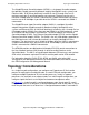
Topology Considerations
In a single-line path configuration, you configure one Expand-over-IP line-handler
process for each path to an adjacent node. In a multi-CPU path configuration, you
configure multiple Expand-over-IP line-handler processes, usually in separate
processors, for each path to an adjacent node. In a multi-line path configuration, you
configure a path that consists of multiple lines between two adjacent nodes.
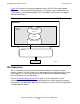
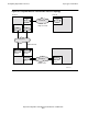
In Figure 8-3, a single-line path is configured between node \A and node \B; a multi-
CPU path that consists of two paths is configured between node \A and node \C; and a
multi-line path that consists of three lines is configured between node \C and node \D.