Fibre Channel ServerNet Adapter Installation and Support Guide Abstract This guide describes how to install, replace, and relocate a Fibre Channel ServerNet adapter (FCSA) in an HP I/O adapter module (IOAM) enclosure. This guide is written for HP service representatives who install or maintain FCSAs. Product Version N.A. Supported Release Version Updates (RVUs) This guide supports G06.28 and all subsequent G-series RVUs and H06.
Document History Part Number Product Version Published 528254-002 N.A. September 2004 528254-006 N.A. July 2005 528254-007 N.A. September 2005 528254-008 N.A. February 2006 528254-012 N.A.
Fibre Channel ServerNet Adapter Installation and Support Guide Glossary Index What’s New in This Guide vii Guide Information vii New and Changed Information Examples Figures viii About This Manual ix Who Should Use This Guide ix What’s in This Guide ix Where to Get More Information x Notation Conventions x 1.
2. Installing an FCSA Contents 2.
3. Replacing an FCSA Contents 3.
A. FCSA Configuration Forms for ESS Connections Contents A. FCSA Configuration Forms for ESS Connections B. FCSA Configuration Forms for Fibre Channel Disk Module (FCDM) Connections Safety and Compliance Glossary Index Examples Example 3-1. Example 3-2. SCF INFO DISK DETAIL Display 3-4 SCF STATUS ADAPTER DETAIL Display 3-5 Figures Figure 1-1. Figure 1-2. Figure 1-3. Figure 1-4. Figure 1-5. Figure 1-6. Figure 1-7. Figure 1-8. Figure 2-1. Figure 2-2. Figure 2-3. Figure 2-4. Figure 3-1. Figure 3-2.
Tables (continued) Contents Tables (continued) Table 2-5. Table 2-6. Table 2-7. Table 2-8. Table 3-1. Table 3-2. Table 3-3. Table 3-4. Table 4-1. Table 4-2. Table 4-3.
Contents Fibre Channel ServerNet Adapter Installation and Support Guide —528254-012 vi
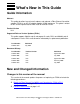
What’s New in This Guide Guide Information Fibre Channel ServerNet Adapter Installation and Support Guide Abstract This guide describes how to install, replace, and relocate a Fibre Channel ServerNet adapter (FCSA) in an HP I/O adapter module (IOAM) enclosure. This guide is written for HP service representatives who install or maintain FCSAs. Product Version N.A. Supported Release Version Updates (RVUs) This guide supports G06.28 and all subsequent G-series RVUs and H06.
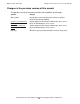
Changes in the previous version of this manual What’s New in This Guide Changes in the previous version of this manual The previous version of the manual contains these additions and changes: Section Change Manual-wide Changed the name of the Disk Drive Enclosure to Fibre Channel Disk Module (FCDM). Section 1, Introduction to the FCSA Added support for Fibre Channel M85xx tape drives via an FCSA on HP NonStop S-series servers.
About This Manual This guide describes how to install, replace, and relocate a Fibre Channel ServerNet adapter (FCSA) in an I/O adapter module (IOAM) enclosure. Who Should Use This Guide This guide is written for HP service representatives who install or maintain FCSAs in an IOAM enclosure. The user of this guide should have knowledge of: • • The OSM Service Connection, part of the HP NonStop Open System Management (OSM) Interface.
About This Manual Where to Get More Information Where to Get More Information Manuals describing the IOAM enclosure in relation to HP NonStop S-series servers are organized into several sets that are fully described in the NonStop S-Series Planning and Configuration Guide. Manuals describing the IOAM enclosure in relation to HP Integrity NonStop NS-Series servers are organized into several sets that are fully described in the NonStop NSSeries Planning Guide.
About This Manual General Syntax Notation computer type. Computer type letters within text indicate C and Open System Services (OSS) keywords and reserved words. Type these items exactly as shown. Items not enclosed in brackets are required. For example: myfile.c italic computer type. Italic computer type letters within text indicate C and Open System Services (OSS) variable items that you supply. Items not enclosed in brackets are required. For example: pathname [ ] Brackets.
Change Bar Notation About This Manual Punctuation. Parentheses, commas, semicolons, and other symbols not previously described must be typed as shown. For example: error := NEXTFILENAME ( file-name ) ; LISTOPENS SU $process-name.#su-name Quotation marks around a symbol such as a bracket or brace indicate the symbol is a required character that you must type as shown. For example: "[" repetition-constant-list "]" Item Spacing.
1 Introduction to the FCSA This section provides an introduction to the Fibre Channel ServerNet adapter (FCSA) for I/O Adapter Module (IOAM) enclosures.
Introduction to the FCSA Overview of the FCSA The FCSA has two ports that allow connection to external, fibre-channel-enabled devices. Figure 1-1 shows the ports on the FCSA. Note. In this manual, the term port refers to the physical connector on the adapter to which the cable is connected and is used for hardware discussions such as adapter location and connectors.
Overview of the FCSA Introduction to the FCSA Figure 1-1. FCSA Ports Port 1 2Gb 1Gb Port 1 Port 2 2Gb 1Gb Port 1 FCSA Fibre Ethernet ports: not available for FCSA Ethernet ports: not available for FCSA D C Ethernet ports: not available for FCSA VST001.vsd FCSAs are installed in slots 1 through 5 of an I/O adapter module (IOAM) enclosure. Because there are two logical modules in an IOAM enclosure, a total of 10 FCSAs can be installed in an enclosure. FCSAs are installed in pairs.
Overview of the FCSA Introduction to the FCSA installed one each in different IOAM enclosures. Figure 1-2 shows the slots available in the IOAM for the FCSA. Figure 1-2.
Introduction to the FCSA FCSA Features FCSA Features • Supports both 2-Gbps or 1-Gbps Fibre Channel protocol. Note. The FCSA supports both 2-Gbps and 1-Gbps Fibre Channel speeds. A 1-Gbps Fibre Channel cable typically has a Subscriber Channel (SC connector) that does not install on an FCSA unless an adapter is used. If the ESS Fibre Channel port is a 1-Gbps port, the link operates at 1-Gbps even if the Fibre Channel cable connected to the FCSA is a 2-Gbps cable.
Introduction to the FCSA FCSA External Connectors, Indicators, and Cables Figure 1-3. Connector Plugs Should be in Place When Cable Is Not in Use Connector Plug VST003.vsd Table 1-1. FCSA Cables Type Length Product ID LC-LC cable, multimode fibre (MMF) 2 meters (m) M8900-02 5m M8900-05 15 m M8900-15 40 m M8900-40 80 m M8900-80 250 m M8900250 The FCSA has a power-status external light-emitting diode (LED) and a fault-indicator LED for the adapter.
FCSA External Connectors, Indicators, and Cables Introduction to the FCSA Figure 1-4. Power-Status and Fault-Indicator LEDs Port 1 2Gb 1Gb 2Gb 1Gb Port 1 FCSA D C Power-status LED (green) Fault-indicator LED (amber) FCSA Power and Fault LEDs new.vsd The FCSA power-status and fault-indicator LEDs are controlled by the internal hardware and indicate the adapter states described in Table 1-2.
FCSA External Connectors, Indicators, and Cables Introduction to the FCSA Table 1-2. Power-Status and Fault-Indicator LEDs LED State Description Green Not lit Adapter is faulty or has been powered off. Lit Adapter is powered. After installing the FCSA, the green power-status LED should come on within a minute. Amber Not lit Adapter is functional. Lit Adapter internal failure or service action is indicated by the software or the technician.
FCSA External Connectors, Indicators, and Cables Introduction to the FCSA Figure 1-5. Port LEDs 2-Gbps link status Port 1 (green) Port 1 2Gb 1Gb 2-Gbps link status Port 2 (green) 1-Gbps link status Port 1 (amber) 1-Gbps link status Port 2 (amber) 2Gb 1Gb Port 1 FCSA D C VST006.
FCSA External Connectors, Indicators, and Cables Introduction to the FCSA The Fibre Channel port status LEDs indicate the activity on the Fibre Channel ports: Hardware State Green LED (2 Gbps) Amber LED (1 Gbps) Power Off Off Off Power On, before firmware download On On Power On, after firmware initialization 1 flash 1 flash Both flashing at the same time Firmware fault 2 flashes 2 flashes Alternate flashing 1 Gbps link UP Off On 2 Gbps link UP On Off Activity at 1 Gbps Off 5 flas
Introduction to the FCSA FCSA External Connectors, Indicators, and Cables Figure 1-6. FCSA Ejector and Label Label Ejector VST007.
Introduction to the FCSA FCSA System Connections FCSA System Connections An FCSA has three primary system connections: • • • Data transfer interface (ServerNet) (connects to the ServerNet X and Y fabrics) Maintenance entity (ME) interface Power interface These connections are on the back of the FCSA and attach to the midplane. Data Transfer Interface (ServerNet) The data transfer interface consists of ports to the ServerNet X and Y fabrics.
Flash Firmware Introduction to the FCSA Flash Firmware The flash firmware contains version information about the operational firmware located in the FCSA FLASH memory. Flash firmware runs the FCSAs used for system load so the processor boot milicode can read the system-load disk. The flash firmware is not used on NonStop S-series servers.
Relationship to the Enterprise Storage System (ESS) Introduction to the FCSA group (Integrity NonStop NS-series server) is in the range 110 through 115. module identifies whether the FCSA is installed in module 2 or 3 of an IOAM enclosure. A module is either 2 or 3. slot is the FCSA physical slot number in the IOAM: Number Description 1 to 5 For the FCSA sac identifies one of the ServerNet Addressable Controllers (SACs) inside the FCSA. SACs are designated either 1 or 2.
Relationship to the Enterprise Storage System (ESS) Introduction to the FCSA Figure 1-7 shows an example of two paths from the processors through the FCSAs to the storage subsystem. More complicated paths are likely, but Figure 1-7 relates the SCF attributes to the storage subsystem path. The SCF attributes shown in the figure are discussed after the figure. Figure 1-7.
Introduction to the FCSA Storage Subsystem SCF Attributes for ESS Connections Storage Subsystem SCF Attributes for ESS Connections The SCF attributes for the paths shown in Figure 1-7 are defined as: primarycpu, backupcpu define the primary and backup processor locations for the DISK process pair. primarylocation, backuplocation define the primary and backup locations (group, module, slot) of the FCSAs for the paths. primarysac, backupsac define the primary and backup ports on the FCSA for the paths.
Introduction to the FCSA Relationship to the Fibre Channel Disk Module (FCDM) Your overall strategy might affect which slots you select for the FCSA installation and the paths you configure between the processors and the disks. Your strategy might consist of general principles, such as: • • • • Use mirroring Use four processors Use slots in different IOAM logical modules or different IOAM enclosures Use LUNs in different ESS systems.
Relationship to the Fibre Channel Disk Module (FCDM) Introduction to the FCSA Figure 1-8. Fibre Channel Disk Module (FCDM) Configuration Attributes primarycpu backupcpu CPU 0 in (1, 1, 50) CPU 2 in (2, 1, 50) ServerNet Y fabric ServerNet X fabric primarylocation backuplocation FCSA in (11, 2, 5) sac1 FCSA in (21, 3, 5) sac1 sac2 sac2 primarysac backupsac primarydeviceid (shelf, bay) A A bay1 A A shelf 2 bay14 B B A A bay1 B shelf 1 B bay14 B B VST026.
Introduction to the FCSA Storage Subsystem SCF Attributes for FCDM Connections Storage Subsystem SCF Attributes for FCDM Connections The SCF attributes for the paths shown in Figure 1-8 are defined as: primarycpu, backupcpu define the primary and backup processor locations for the DISK process pair. primarylocation, backuplocation define the primary and backup locations (group, module, slot) of the FCSAs for the paths. primarysac, backupsac defines the primary and backup ports.
Introduction to the FCSA Relationship to Fibre Channel Tape Drives Fibre Channel ServerNet Adapter Installation and Support Guide —528254-012 1- 20
2 Installing an FCSA This section describes how to install a Fibre Channel ServerNet adapter (FCSA) in an I/O adapter module (IOAM) enclosure.
Installing an FCSA Fibre Channel Disk Module (FCDM) Connection To obtain the WWNs of the FCSA, you must download the firmware. To download the firmware: 1. Use SCF to add the DISK object. 2. Then start the DISK object. (The DISK object does not have to come up.) 3. After the firmware has been downloaded, determine the FCSA WWNs: a. Issue the STATUS ADAPTER, DETAIL or STATUS ADAPTER, SACS command. b. Examine the Port Name and Node Name fields in the resulting display.
Tape Drive Connection Installing an FCSA Tape Drive Connection Connections between host tape processes on NonStop NS-series systems and SCSI attached N1525A tape drives require the use of a M8201 Fibre Channel to SCSI router, which you install inside the system cabinet. For information about installing the Fibre Channel to SCSI router and connecting it to the FCSA, see the M8201 Fibre Channel to SCSI Router Installation Guide.
Installing an FCSA Start Completing the Configuration Forms ESS Connections For connections to an ESS: • • Define different FC switches for the primary and backup DISK paths. Define different ESSes for the primary and backup DISK images. For more information about fault-tolerance planning, see the Modular I/O Installation and Configuration Guide.
Start Completing the Configuration Forms Installing an FCSA This information is on the FCSA’s physical label. (See Figure 1-6 on page 1-11.) 2. Record the FCSA’s physical location on your FCSA Configuration Form as described in Table 2-2. Table 2-2. How to Fill in the Location of the FCSA Field Where to Obtain the Information Date Enter the date that you are installing the FCSA. System Name Use the scroll keys on the LCD on the I/O switch in the IOAM to scroll to the system name.
Installing an FCSA Start Completing the Configuration Forms Table 2-3. SCF ADD DISK Command Attribute Names for ESS Connections (page 1 of 2) SCF Attribute Name/ Attribute Value Description PRIMARYCPU number The attribute values specify the primary and backup processor locations of the DISK object.
FCDM Connections Installing an FCSA Table 2-3. SCF ADD DISK Command Attribute Names for ESS Connections (page 2 of 2) SCF Attribute Name/ Attribute Value Description MIRRORPORTNAME number The attribute values specify the WWNs of the mirror primary and backup Fibre Channel ports on the ESS. Obtain this information from the ESS administrator. (The choices should be guided by the overall fault-tolerant strategy for the storage subsystem configuration.
Gather the Proper Tools Installing an FCSA • Decide which of the Fibre Channel disks serve as primary disks and which serve as mirror disks HP provides two forms to help in these tasks: • • Configuration Form for Primary and Backup Disks Configuration Form for Mirror and Mirror Backup Disks HP also provides a SCF Disk Volume Configuration Form to help you record each primary and mirrored disk that form part of a disk volume.
Check That the Slot Was Not Previously Configured Installing an FCSA Figure 2-1.
Installing an FCSA Install the FCSA Install the FCSA Table 2-4. Installation Checklist Step Description Topic Location 1. Unpack and Inspect the FCSA Page 2-10 2. Install the FCSA Page 2-11 Unpack and Inspect the FCSA Note. Whenever you handle an FCSA, follow standard operating practices to avoid damage to the equipment. See Review Standard Operating Practices on page 2-8. 1. Put on an ESD wrist strap and attach the grounding clip to the antistatic mat. 2.
Installing an FCSA Install the FCSA Install the FCSA 1. Disconnect the grounding clip of your ESD wrist strap from the antistatic mat and connect it to an unpainted metal surface on the FCSA. 2. Grasp the FCSA by its purple ejector latch in one hand, while supporting the bottom edge of the FCSA with the other hand. Carry the FCSA to the rear of the IOAM enclosure. Set the FCSA down on an antistatic mat with the ejector latch at the top. Note. The FCSA weighs approximately 7.25 pounds (3 kilograms). 3.
Install the FCSA Installing an FCSA Figure 2-2. Inserting the FCSA Into the Enclosure VST011.vsd 5. Press down and back on the latch. The latch slides under the top lip of the frame and secures the adapter in place. The ejector latch clicks when the adapter is fully seated. 6. Disconnect the grounding clip of your ESD wrist strap from the rack or enclosure. 7.
Label the Cables Installing an FCSA Figure 2-3. Fibre Channel Cables VST012.vsd The green power-on LED at the bottom of the adapter should now be lit. If the LED is not lit, either reseat the FCSA or install a different FCSA. Label the Cables 1. Find the group, module, and slot of the IOAM enclosure in which the FCSA is installed. (See Figure 1-2 on page 1-4.) 2. Tag the Fibre Channel cables connected to the FCSA with physical labels, preferably at both cable ends.
Verify the Installation of the FCSA Installing an FCSA Verify the Installation of the FCSA Table 2-5. Installation Verification Checklist Step Description Topic Location 1. Verify the Hardware Installation Page 2-14 2. Verify the Presence of the FCSA in the Configuration Database Page 2-14 3. Troubleshoot the Installation Page 2-15 Verify the Hardware Installation Verify the installation of the FCSA by examining the FCSA’s status LEDs.
Installing an FCSA Troubleshoot the Installation Troubleshoot the Installation If either of the following conditions occur: • • The SCF STATUS SAC command shows that the FCSA SAC object is still in the STARTING state after a few minutes, or The OSM Service Connection indicates that the resource needs attention: check for event messages in the Event Message Service (EMS) log. Use the OSM Event Viewer to view the EMS log.
Installing an FCSA Start the Disk ADD the Disk Using the information that you obtained in Start Completing the Configuration Forms on page 2-4, configure an SCF disk volume object for use with the ESS. The example shows an SCF ADD command that adds a mirrored DISK volume object for a hardware configuration consisting of two FCSA adapters. Because you might have to run this configuration procedure several times, it is best to create a command file.
Installing an FCSA Obtain the Fibre Channel Port WWNs and Complete the FCSA to ESS Configuration Form Obtain the Fibre Channel Port WWNs and Complete the FCSA to ESS Configuration Form Table 2-8. Obtaining the WWN Checklist Step Description Topic Location 1. Obtain the Adapter Status Page 2-18 2.
Obtain the Fibre Channel Port WWNs and Complete the FCSA to ESS Configuration Form Installing an FCSA Obtain the Adapter Status Enter the STATUS ADAPTER, DETAIL command with the detail option for the FCSA: 3-> status $ZZSTO.#FCSA.GRP-11.MOD-3.SLOT-5, d STORAGE - Detailed Adapter Type..... Flash Boot....... Flash Firmware... Location......... Part ID.......... Power-1.......... Revision Level... Tracking Number.. Status ADAPTER \MYSYS.$ZZSTO.#FCSA.GRP-11.MOD-3.SLOT-5 FCSA T0612G06 Flash Update Active....
Connect External Paths Installing an FCSA The WWN of each SAC is identified by the Port Name field. In this example, the WWN of SAC 1 is 50060B00001D535C, and SAC 2 is 50060B00001D535E. Complete the Configuration Forms Complete the FCSA to ESS Connection form. Figure 2-4 shows a sample completed form. Figure 2-4.
Installing an FCSA Connect External Paths 1. Have the FCSA connected to the FC switch or ESS (depending on whether you are using direct connect or switched connect). Caution. Do not connect the Fibre Channel cables to the FC switch or the ESS yourself. The ESS or FC switch administrator must perform this task. 2. Update the WWN zoning in the SAN so the ESS recognizes the FCSA. Note. Adding or updating WWNs in the ESS is not required if the FCSA ports are directly connected to the ESS FC ports. 3.
Disk Configuration (FCDM Connection) Installing an FCSA Disk Configuration (FCDM Connection) For information about disk configuration for FCDMs containing M8xxx disks, see the SCF Reference Manual for the Storage Subsystem. Verify the Disk Configuration To check that the DISK object was successfully added to the configuration database, issue the SCF STATUS ADAPTER adapter-name, DETAIL command. STORAGE - Detailed Adapter Type..... Flash Boot....... Flash Firmware... Location......... Part ID..........
Installing an FCSA Troubleshoot the Disk Configuration Troubleshoot the Disk Configuration If you receive errors when you try to start the DISK object, go into the OSM Event Viewer, specify Real Time, and view the service log ($ZLOG). ($ZLOG has the lowest-level errors.) Error -2 or 190 If the file system returns an error -2 or 190 when you issue the START DISK command, you might need to initialize the disk by using the INITIALIZE DISK command.
Tape Configuration Installing an FCSA Tape Configuration Note. For a list of tape devices supported for use with NonStop S-series servers, see the NonStop S-Series Hardware Installation and FastPath Guide. For a list of tape devices supported for use with Integrity NS-series servers, see the NonStop NS-Series Hardware Installation Guide. Note. For information about configuring Fibre Channel tape drives, refer to the manual for the particular tape drive product.
Verify the Tape Configuration Installing an FCSA This example command adds two TAPE objects using the same SAC to communicate with two SCSI tape devices through the ports of an M8201 router: -> -> -> -> -> -> ADD TAPE $tape1, & LOCATION (110,3,2),& LUN 1 PORTNAME 100000E00Y00N000 SAC 2, & SENDTO STORAGE > ADD TAPE $tape2, & -> LOCATION (110,3,2),& -> LUN 3 -> PORTNAME 100000E00Y00N000 -> SAC 2, & -> SENDTO STORAGE For more information about installing and configuring a M8201 Fibre Channel to SCSI router
Installing an FCSA Verify the Tape Configuration For information about added tape drives, issue a INFO ADAPTER, DETAIL command: STORAGE - Detailed Info ADAPTER \IO.$ZZSTO.#FCSA.GRP-15.MOD-2.SLOT-2 Access List................... 0,1,2,3,4,5,6,7,8,9,10,11,12,13,14,15 Location (Group,Module,Slot).. (15,2,2) ServerNet Addressable Controllers: SAC \IO.$ZZSTO.#FCSA.SAC-1.GRP-15.MOD-2.
Installing an FCSA Verify the Tape Configuration Fibre Channel ServerNet Adapter Installation and Support Guide —528254-012 2- 26
3 Replacing an FCSA This section describes how to replace a Fibre Channel ServerNet adapter (FCSA) in an IOAM enclosure. You might need to replace an FCSA if it has failed or partially failed. If POST fails and an OSM alarm is generated on the FCSA SAC, you must replace the FCSA. If you are moving the FCSA to a different slot, see Section 4, Relocating an FCSA.
Replacing an FCSA Prepare to Replace an FCSA the ESS subsystem recognizes the new FCSA WWNs, but if certain security parameters are set within the ESS, the ESS subsystem does not use the new WWNs automatically. If the ESS subsystem does not recognize the FCSA WWNs, when you restart the DISK object, the NonStop server returns Error 66.
Replacing an FCSA Gather the Proper Tools Gather the Proper Tools See Gather the Proper Tools on page 2-8. Print the FCSA Forms Print two copies of the FCSA Configuration Form (located in Appendix A, FCSA Configuration Forms for ESS Connections) and use one to record information about the FCSA that you are replacing and the other to record information about the new FCSA.
Replacing an FCSA Identify the Devices Example 3-1. SCF INFO DISK DETAIL Display 1-> INFO DISK $DS101, DETAIL STORAGE - Detailed Information Magnetic Common Disk Configuration Information: . . . Disk Type Specific Information: . . . Primary Path Information: Adapter............................... Disk Device ID / Port Name............ Disk Device LUN....................... Location (Group,Module,Slot).......... SAC Name.............................. SAC Number............................ $ZZSTO.#FCSA.
Replacing an FCSA Identify the Devices Example 3-2. SCF STATUS ADAPTER DETAIL Display 3-> STATUS $ZZSTO.#FCSA.GRP-11.MOD-2.SLOT-1, DETAIL STORAGE - Detailed Status ADAPTER \MYSYS.$ZZSTO.#FCSA.GRP-11.MOD-2.SLOT-1 Adapter Type..... FCSA Flash Boot........T0612G06 Flash Update Active...Done Flash Firmeare....T0630G06 Flash Update Result...Init Location......... (21,2,1) Number of SACs......... 2 Part ID.......... 526217 POST Result............ PASSED Power-1.......... ON Power-2................
Replacing an FCSA Switch the Paths to Another FCSA Switch the Paths to Another FCSA Issue the SWITCH ADAPTER, AWAY command to move all the devices’ active paths to an alternate path. (For more information about the SWITCH ADAPTER command, see the SCF Reference Manual for the Storage Subsystem.) ->SWITCH ADAPTER $ZZSTO.#FCSA.GRP-11.MOD-2.SLOT-1 , AWAY This command moves the paths to their alternates and warns you if a path cannot be switched.
Replacing an FCSA Replace the FCSA Replace the FCSA This procedure refers you to OSM to perform the Replace action but provides illustrations and information that supplements the procedures in OSM help. Table 3-2. Replacement Checklist Step Description 1. Review Standard Operating Practices 2. Use OSM to Replace the Adapter 3. Download the Firmware 4. Verify the Installation of the FCSA Note. Whenever you handle an FCSA, follow standard operating practices to avoid damage to the equipment.
Replacing an FCSA Use OSM to Replace the Adapter 6. Physically replace the adapter: a. Remove the installed adapter and install the new one. For removal, see Figure 3-1, Figure 3-2, and the text explaining them. For installation, see Install the FCSA on page 2-11, b. If the FCSA ports are connected to the FC switch and not directly to the ESS FC ports, update the WWN zoning in the SAN so the ESS recognizes the FCSA. c. Add WWNs to the ESS host group configurations as appropriate. 7.
Replacing an FCSA Use OSM to Replace the Adapter Figure 3-1. Pressing Down on the Latch Frame Lip Press down and back on ejector VST015.vsd The procedures in OSM include the step of grasping the FCSA by its ejector latch in one hand and pulling it out of the slot while supporting the bottom edge of the FCSA with the other hand. Figure 3-2 shows this step. Note. The FCSA weighs approximately 7.
Replacing an FCSA Download the Firmware Figure 3-2. Removing the FCSA VST016.vsd Download the Firmware To download the application firmware, complete the tasks listed in Disk Configuration (ESS Connection) on page 2-15. Verify the Installation of the FCSA To verify the installation, follow the procedure described in Verify the Installation of the FCSA on page 2-14. Update the Firmware You can use both OSM and SCF to update the firmware.
Replacing an FCSA Download Firmware for One FCSA Table 3-3. Update the Firmware Checklist Step Description 1. Download Firmware for One FCSA 2. Download Firmware for Multiple FCSAs Download Firmware for One FCSA To download the firmware by using OSM: 1. Log on to the OSM Service Connection. 2. Expand the tree pane to locate and select the FCSA you want to check. 3. Right-click the FCSA object and select Actions. 4.
Replacing an FCSA Resume Operations some of the FCSAs are down-rev, you can easily select all down-rev FCSAs by selecting Down-rev in the Filter by list (Down-rev appears as an option only if one or more FCSAs have down-rev firmware.) 6. Select the FCSAs you want to update and click Add to move them to the lower list (or click Add All to move all FCSAs listed). 7. Click Perform Action to initiate a flash boot firmware update on all FCSAs appearing in the lower list. 8.
Replacing an FCSA Verify That the Connected Devices Are Operational Verify That the Connected Devices Are Operational Issue the STATUS ADAPTER DETAIL command on the new adapter to ensure that all the disks that should be active are active: ->STATUS ADAPTER ZZSTO.#FCSA.GRP-11.MOD-2.SLOT-1, DETAIL Obtain the Fibre Channel Port WWNs and Complete the FCSA to ESS Configuration Form Table 3-5. Obtaining the WWN Checklist Step Description Topic Location 1. Obtain the Adapter Status Page 3-14 2.
Replacing an FCSA Obtain the Fibre Channel Port WWNs and Complete the FCSA to ESS Configuration Form Enter the STATUS ADAPTER, DETAIL command with the detail option for the FCSA: 3-> status $ZZSTO.#FCSA.GRP-11.MOD-3.SLOT-5, d STORAGE - Detailed Adapter Type..... Flash Boot....... Flash Firmware... Location......... Part ID.......... Power-1.......... Revision Level... Tracking Number.. Status ADAPTER \MYSYS.$ZZSTO.#FCSA.GRP-11.MOD-3.SLOT-5 FCSA T0612G06 Flash Update Active....
Replacing an FCSA Connect External Paths The WWN of each SAC is identified by the Port Name field. In this example, the WWN of SAC 1 is 50060B00001D535C, and SAC 2 is 50060B00001D535E. Complete the Configuration Forms Complete the FCSA to ESS Connection form. Figure 3-3 shows a sample completed form. Figure 3-3.
Replacing an FCSA Connect External Paths 1. Have the FCSA connected to the FC switch or ESS (depending on whether you are using direct connect or switched connect). Caution. Do not connect the Fibre Channel cables to the FC switch or the ESS yourself. The ESS or FC switch administrator must perform this task. 2. Update the WWN zoning in the SAN so the ESS recognizes the FCSA. Note. Adding or updating WWNs in the ESS is not required if the FCSA ports are directly connected to the ESS FC ports. 3.
4 Relocating an FCSA This section describes how to relocate an FCSA that has been previously installed in an IOAM enclosure. Note. An FCSA can be relocated without shutting down the system. Overview of FCSA Replacement Procedures Page 4-1 Prepare to Relocate an FCSA Page 4-2 Remove and Relocate the FCSA Page 4-2 Verify the Installation of the FCSA Page 4-3 Resume Operations Page 4-4 Note. Whenever you handle an FCSA, follow standard operating practices to avoid damage to the equipment.
Prepare to Relocate an FCSA Relocating an FCSA Prepare to Relocate an FCSA Table 4-1. Preparation Checklist Step Description 1. For the proper tools, refer to Gather the Proper Tools on page 2-8. 2. Follow the procedure described in Print the FCSA Forms on page 3-3, but you only need one form instead of the two indicated in that procedure. 3. Follow the procedure described in Determine the Physical Location of the FCSA on page 3-3. 4.
Relocating an FCSA Review Standard Operating Practices Review Standard Operating Practices See Review Standard Operating Practices on page 2-8 and Figure 2-1 on page 2-9. Remove the Adapter 1. Disconnect the Fibre Channel cables one at a time by squeezing the plastic retaining clip at the end of the cable and gently pulling. 2. Protect the equipment from electrostatic discharge: a. Place an antistatic table mat on a flat horizontal work surface near the IOAM enclosure. b. Put on an ESD wrist strap. c.
Relocating an FCSA Resume Operations Resume Operations Table 4-3. Update the DISK Objects Checklist Step Description 1. Connect External Devices 2. Alter or Add DISK Objects 3. Restart the Connected Devices 4. Troubleshooting Connect External Devices Complete the procedure for Connect External Paths on page 2-19.
A FCSA Configuration Forms for ESS Connections This appendix provides forms for recording information about your FCSAs. You are authorized to photocopy this form only for the purpose of installing and configuring your HP system. When you complete the forms, place them in your Documentation Packet. For more information about the Documentation Packet, see the NonStop S-Series Planning and Configuration Guide or the NonStop NS-Series Planning Guide.
FCSA Configuration Forms for ESS Connections FCSA Configuration Form Identifying Information About the FCSA Date:_______________ Location of the FCSA Part Number: System Name: Track ID: Group: SAC1 WWN: Module: SAC2 WWN: Slot: Information for Adding Disks to the Configuration Database Primary CPU: Backup CPU: Primary Location: Backup Location: Mirror Primary Location: Mirror Backup Location: Primary SAC: Backup SAC: Mirror Primary SAC: Mirror Backup SAC: Primary Port: Backup Port: Mir
FCSA Configuration Forms for ESS Connections Fibre Channel ServerNet Adapter (FCSA) Configuration Form Primary LUN Information Group: Module: Primary LUN Numbers for SAC1 Slot: Primary LUN Numbers for SAC2 VST019.
FCSA Configuration Forms for ESS Connections Fibre Channel ServerNet Adapter (FCSA) Configuration Form Mirror LUN Information Group: Module: Mirror LUN Numbers for SAC1 Slot: Mirror LUN Numbers for SAC2 VST020.
FCSA Configuration Forms for ESS Connections Fibre Channel ServerNet Adapter (FCSA) Configuration Form Primary Port Information Group: Module: Primary Port Numbers for SAC1 Slot: Primary Port Numbers for SAC2 VST021.
FCSA Configuration Forms for ESS Connections Fibre Channel ServerNet Adapter (FCSA) Configuration Form Backup Port Information Group: Module: Backup Port Numbers for SAC1 Slot: Backup Port Numbers for SAC2 VST022.
FCSA Configuration Forms for ESS Connections Fibre Channel ServerNet Adapter (FCSA) Configuration Form Mirror Primary Port Information Group: Module: Mirror Primary Port Numbers for SAC1 Slot: Mirror Primary Port Numbers for SAC2 VST023.
FCSA Configuration Forms for ESS Connections Fibre Channel ServerNet Adapter (FCSA) Configuration Form Mirror Backup Port Information Group: Module: Mirror Backup Port Numbers for SAC1 Slot: Mirror Backup Port Numbers for SAC2 VST024.
FCSA Configuration Forms for ESS Connections FCSA to ESS Connection Form FCSA Administrator Name: S A C NonStop System Name G, M, S # Date: WorldWide Name of SAC WorldWide Name of ESS VST018.
FCSA Configuration Forms for ESS Connections Fibre Channel ServerNet Adapter Installation and Support Guide— 528254-012 A -10
B FCSA Configuration Forms for Fibre Channel Disk Module (FCDM) Connections This appendix provides forms for recording information about your FCSAs and the Fibre Channel disk drives that interface to them. You are authorized to photocopy this form only for the purpose of installing and configuring your HP system. When you complete the forms, place them in your Documentation Packet. For more information about the Documentation Packet, see the the NonStop NS-Series Planning Guide.
FCSA Configuration Forms for Fibre Channel Disk Module (FCDM) Connections Configuration Form for Primary and Backup Disks Part 1 Date:_______________ FCSA Information Identifying Information About the FCSA Location of the FCSA Part Number: System Name: Track ID: Group: SAC Module: Slot: Identifying Information About the FCSA Location of the FCSA Part Number: System Name: Track ID: Group: SAC Module: Slot: VST030.
FCSA Configuration Forms for Fibre Channel Disk Module (FCDM) Connections Configuration Form for Primary and Backup Disks Part 2 Date:_______________ Disk Information Shelf number 1 2 3 4 5 6 7 8 9 10 11 12 13 14 Bay number Shelf number 1 2 3 4 5 6 7 8 9 10 11 12 13 14 Bay number Shelf number 1 2 3 4 5 6 7 8 9 10 11 12 13 14 Bay number Shelf number 1 2 3 4 5 6 7 8 9 10 11 12 13 14 Bay number VST031.
FCSA Configuration Forms for Fibre Channel Disk Module (FCDM) Connections Date:_______________ Configuration Form for Mirror and Mirror-Backup Disks Part 1 FCSA Information Identifying Information About the FCSA Location of the FCSA Part Number: System Name: Track ID: Group: SAC Module: Slot: Identifying Information About the FCSA Location of the FCSA Part Number: System Name: Track ID: Group: SAC Module: Slot: VST032.
FCSA Configuration Forms for Fibre Channel Disk Module (FCDM) Connections Configuration Form for Mirror and Mirror-Backup Disks Part 2 Date:_______________ Disk Information Shelf number 1 2 3 4 5 6 7 8 9 10 11 12 13 14 Bay number Shelf number 1 2 3 4 5 6 7 8 9 10 11 12 13 14 Bay number Shelf number 1 2 3 4 5 6 7 8 9 10 11 12 13 14 Bay number Shelf number 1 2 3 4 5 6 7 8 9 10 11 12 13 14 Bay number VST033.
FCSA Configuration Forms for Fibre Channel Disk Module (FCDM) Connections Date:_______________ SCF Disk Volume Configuration Form Disk Volume Name: Backup CPU Primary CPU System Name: Primary Disk Primary path Group: Module: Slot: SAC Shelf Bay Module: Slot: SAC Shelf Bay Module: Slot: SAC Shelf Bay Module: Slot: SAC Shelf Bay Backup path Group: Mirror Disk Mirror path Group: Mirror backup path Group: Disk Volume Name: Backup CPU Primary CPU System Name: Primary Disk Primary p
Safety and Compliance This sections contains three types of required safety and compliance statements: • • • Regulatory compliance Waste Electrical and Electronic Equipment (WEEE) Safety Regulatory Compliance Statements The following regulatory compliance statements apply to the products documented by this manual. FCC Compliance This equipment has been tested and found to comply with the limits for a Class A digital device, pursuant to part 15 of the FCC Rules.
Safety and Compliance Regulatory Compliance Statements Korea MIC Compliance Taiwan (BSMI) Compliance Japan (VCCI) Compliance This is a Class A product based on the standard or the Voluntary Control Council for Interference by Information Technology Equipment (VCCI). If this equipment is used in a domestic environment, radio disturbance may occur, in which case the user may be required to take corrective actions.
Regulatory Compliance Statements Safety and Compliance European Union Notice Products with the CE Marking comply with both the EMC Directive (89/336/EEC) and the Low Voltage Directive (73/23/EEC) issued by the Commission of the European Community.
SAFETY CAUTION Safety and Compliance SAFETY CAUTION The following icon or caution statements may be placed on equipment to indicate the presence of potentially hazardous conditions: DUAL POWER CORDS CAUTION: “THIS UNIT HAS MORE THAN ONE POWER SUPPLY CORD. DISCONNECT ALL POWER SUPPLY CORDS TO COMPLETELY REMOVE POWER FROM THIS UNIT." "ATTENTION: CET APPAREIL COMPORTE PLUS D'UN CORDON D'ALIMENTATION. DÉBRANCHER TOUS LES CORDONS D'ALIMENTATION AFIN DE COUPER COMPLÈTEMENT L'ALIMENTATION DE CET ÉQUIPEMENT".
Safety and Compliance Waste Electrical and Electronic Equipment (WEEE) HIGH LEAKAGE CURRENT To reduce the risk of electric shock due to high leakage currents, a reliable grounded (earthed) connection should be checked before servicing the power distribution unit (PDU).
Safety and Compliance Customer Installation and Servicing of Equipment Customer Installation and Servicing of Equipment The following statements pertain to safety issues regarding customer installation and servicing of equipment described in this manual. • • Keep door closed for normal operation. The equipment must be installed near the receptacles for the power cords, and the receptacles must be easily accessible to the user. Caution. If this unit has more than one power supply cord.
Safety and Compliance Applicabilité des procédures, des directives et des exemples MISE EN GARDE. Ne pas toucher au connecteur d'alimentation C.C. de l'unité PMF remplaçable par le client du S7400/S7x000 après avoir débranché le cordon d'alimentation C.C. de cette unité. Des risques de chocs électriques dangereux peuvent subsister pendant quinze (15) secondes après le débranchement du câble.
Safety and Compliance Anwendbarkeit von Verfahren, Anleitungen und Beispielen Anwendbarkeit von Verfahren, Anleitungen und Beispielen WARNUNG. Die in diesem Handbuch enthaltenen Verfahren und Anleitungen und die Beispiele von Verfahren und Anleitungen gelten nur für die in den NonStop-S-Serie-Servern vorgefundenen Systemgehäuse und Komponenten, die in der Dokumentation der NonStop-SSerie-Server beschrieben werden. Versuchen Sie nicht, diese Anleitungen mit anderen HPNonStop-System-Geräten zu benutzen.
Safety and Compliance • Veiligheidsinstructies voor de consument Udstyret skal installeres i nærheden af stikkontakterne til netledningerne, og stikkontakterne skal være let tilgængelige for brugeren. ADVARSEL! Berør ikke jævnstrøms forbindelsesstikket på S7400/S7x000 PMF-enheden, der kan udskiftes af kunden, når du har afbrudt jævnstrøms netkablet fra enheden, der kan udskiftes af kunden. Der er risiko for alvorligt stød i op til 15 sekunder efter, at kablet afbrydes.
Safety and Compliance Veiligheidsinstructies voor de consument Veiligheidsinstructies voor de consument Installatie en onderhoud van apparatuur door de klant De volgende veiligheidsinstructies betreffen de installatie en het onderhoud door de klant van de in deze handleiding beschreven apparatuur. • • Houd bij normaal bedrijf de deur gesloten. De apparatuur moet nabij contactdozen voor stroomkabels worden geïnstalleerd en de contactdozen moeten voor de gebruiker gemakkelijk bereikbaar zijn.
Safety and Compliance Informações de segurança para os consumidores Informações de segurança para os consumidores Instalação e manutenção do equipamento pelo cliente As seguintes informações se referem a questões de segurança relacionadas à instalação e manutenção, pelo cliente, do equipamento descrito neste manual. • • Para garantir o funcionamento normal, mantenha a porta fechada. O equipamento deve ser instalado próximo das tomadas, e o usuário deve ter acesso fácil às tomadas. AVISO.
Safety and Compliance Meddelanden beträffande konsumentsäkerhet Meddelanden beträffande konsumentsäkerhet Kundutförd installation och service De följande meddelandena beskriver säkerhetsföreskrifter för kundutförd installation och service av utrustning som beskrivs i denna manual: • • Dörren skall vara stängd under normal drift. Utrustningen bör monters nära eluttag för nätsladdar. Nätsladdarna måste vara lättillgängliga.
Safety and Compliance Kundutförd installation och service S7400/ S7x000 S7400/ S7x000 Fibre Channel ServerNet Adapter Installation and Support Guide—528254-012 Statements- 13
Safety and Compliance Kundutförd installation och service Fibre Channel ServerNet Adapter Installation and Support Guide—528254-012 Statements- 14
Glossary For a glossary of NonStop S-series and Integrity NonStop NS-series terms, see the NonStop Server Glossary in the NonStop Technical Library (NTL).
Glossary Fibre Channel ServerNet Adapter Installation and Support Guide— 528254-012 Glossary- 2
Index A ADD DISK command 2-16 ADD DISK command example, ESS disk 2-16 ALTER DISK command 4-4 Amber LED 1-8 Antistatic table mat 2-10, 4-3 B BACKUPCPU 2-16 backupcpu 1-16, 1-19, 2-6 BACKUPLOCATION 2-16 backuplocation 1-16, 1-19, 2-6 BACKUPPORTNAME 2-16 backupportname 1-16, 2-6 BACKUPSAC 2-16 backupsac 1-16, 2-6 bay 1-19 C Cables caution 1-5, 2-12 descriptions of 1-6 labeling 2-13, 3-6 part numbers for 1-6 Cable, LC-LC, multimode 1-6 Checking for damaged pins 2-14 Command View 2-6 Configuration database 1-1
Index F ESS See Enterprise Storage System (ESS) Ethernet ports 1-2 Events Event Message Service (EMS) log 2-15 OSM Event Viewer 2-15 F Fault tolerance 1-16, 2-3 Fault-indicator LED 1-6, 1-7, 1-8 FCDM See Fibre Channel Disk Module (FCDM) FCSA weight 2-11 Fibre cables, caution 1-5 Fibre Channel Disk Module (FCDM) 1-17/1-19 Fibre Channel ServerNet adapter (FCSA) checking for damaged pins 2-14 configuration form 2-4 determining physical location of 3-3 ESS connection, configuration form A-1/A-9 FCSA planning
Index M LCD 2-5 LC-LC cable 1-6 LED fault-indicator 1-6, 1-7, 1-8 power-status 1-6, 1-7, 1-8 Location 3-3 Logical modules 1-3 Logical unit See LUN LUN 1-14, 2-1, 2-6 M M8201 SCSI to Fibre Channel converter 2-23 M8840 product ID 1-1 Maintenance entity (ME) connection 1-12 MBACKUPLOCATION 2-16, 4-4 MBACKUPPORTNAME 2-16 mbackupportname 2-7 MBACKUPSAC 2-16 mbackupsac 2-6 MIRRORLOCATION 2-16 mirrorlocation 2-6 MIRRORLUN 2-16 mirrorlun 2-7 MIRRORPORTNAME 2-16 mirrorportname 2-7 MIRRORSAC 2-16 mirrorsac 2-6 mod
Index S S SAC 1-2 sac 1-14 SAN 3-1 SC connector 1-5 SCF attributes BACKUPCPU 2-16 backupcpu 1-16, 1-19, 2-6 BACKUPLOCATION 2-16 backuplocation 1-16, 1-19, 2-6 BACKUPPORTNAME 2-16 backupportname 1-16, 2-6 BACKUPSAC 2-16 backupsac 1-16, 2-6 MBACKUPLOCATION 2-16, 4-4 MBACKUPPORTNAME 2-16 mbackupportname 2-7 MBACKUPSAC 2-16 mbackupsac 2-6 MIRRORLOCATION 2-16 mirrorlocation 2-6 MIRRORLUN 2-16 mirrorlun 2-7 MIRRORPORTNAME 2-16 mirrorportname 2-7 MIRRORSAC 2-16 mirrorsac 2-6 of storage subsystem 1-16 PRIMARYCPU
Index T System name 2-5 T Tools needed for installation 2-8 Track ID 2-4 Troubleshooting adapter configuration 2-14 DISK configuration 2-22 disk configuration 2-22 installation 2-15 U Unpacking a FCSA 2-10 V Verifying installation of a FCSA 2-14 W Weight, FCSA 2-11 Worldwide names (WWN) See WWN WWN FCSA 2-1, 2-4, 2-19 formats 2-6 Z Zones 1-14, 2-20, 3-1, 4-1 Special Characters $ZLOG 2-22 $ZZSTO 2-5 Fibre Channel ServerNet Adapter Installation and Support Guide—528254-012 Index -5
Index Special Characters Fibre Channel ServerNet Adapter Installation and Support Guide—528254-012 Index -6