M8609A Tabletop Tape Drive Installation and User’s Guide Abstract This guide provides information about installing, operating, and troubleshooting the M8609A tabletop tape drive on an HP NonStop server. This guide is written for those who install or maintain the M8609A tape drive. Product Version N.A. Supported Release Version Updates (RVUs) This publication supports J06.03 and all subsequent J-series RVUs and H06.14 and all subsequent H-series RVUs until otherwise indicated by its replacement publication.
Document History Part Number Product Version 546013-001 N.A.
M8609A Tabletop Tape Drive Installation and User’s Guide Glossary Index What’s New in This Manual v Manual Information v New and Changed Information Examples Figures Tables v About This Manual vii Supported Products and Features Notation Conventions vii vii 1. Overview and Features Overview 1-1 Features 1-2 Specifications 1-2 2. Installing and Configuring the Tape Drive for the NonStop NSSeries Server Installation 2-1 Configuration 2-5 3.
A. Specifications Contents Taking Care of Cartridges 4-5 Operating and Storage Environment 4-5 Cartridge Is Jammed 4-6 The Tape Drive Will Not Accept a Cartridge (or Ejects It Immediately) A. Specifications Tape Drive Components Weights Power A-2 Technical Specifications A-2 Fiber Cables A-3 Cartridge Specifications A-4 A-1 Safety and Compliance Index Examples Figures Figure 1-1. Figure 2-1. Figure 2-2. Figure 2-3. Figure 2-4. Figure 3-1. Figure 3-2. Figure 3-3. Figure 3-4. Figure 3-5. Figure 3-6.
Contents Table A-4. Table A-5. Table A-6. Table A-7.
Contents M8609A Tabletop Tape Drive Installation and User’s Guide—546013-001 iv
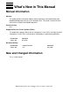
What’s New in This Manual Manual Information M8609A Tabletop Tape Drive Installation and User’s Guide Abstract This guide provides information about installing, operating, and troubleshooting the M8609A tabletop tape drive on an HP NonStop server. This guide is written for those who install or maintain the M8609A tape drive. Product Version N.A. Supported Release Version Updates (RVUs) This publication supports J06.03 and all subsequent J-series RVUs and H06.
What’s New in This Manual New and Changed Information M8609A Tabletop Tape Drive Installation and User’s Guide—546013-001 vi
About This Manual Supported Products and Features This document describes products and features that are not yet available on systems running J-series or H-series RVUs. These products and features include: • • • CLuster I/O Modules (CLIMs) The Cluster I/O Protocols (CIP) subsystem Serial attached SCSI (SAS) disk drives and their enclosures Notation Conventions Hypertext Links Blue underline is used to indicate a hypertext link within text.
Hypertext Links About This Manual M8609A Tabletop Tape Drive Installation and User’s Guide—546013-001 viii
1 Overview and Features This section includes: Overview 1-1 Features 1-2 Overview The tape drive is a LTO Ultrium Generation 4 single cartridge loader unit. It is designed for backup operations for the NonStop NS-series server. The tape drive only comes in a tabletop configuration. This tape drive connects to the Fibre Channel ServerNet adapter (FCSA) on the NonStop server by a fiber-optic cable. Figure 1-1 shows how the tape drive connects to the NonStop NS-series server. Figure 1-1.
Overview and Features Features Features The tape drive allows the user to back up a high data capacity at a high speed. When operating in a noncompressed mode, the tape drive has a native transfer rate of up to 120 megabytes per second. When operating in the compressed mode, the maximum transfer rate is up to 240 megabytes per second. Specifications For the tape drive’s specifications, refer to Appendix A, Specifications.
2 Installing and Configuring the Tape Drive for the NonStop NS-Series Server This section includes: Installation 2-1 Configuration 2-5 Installation 1. Unpack and check the shipment. 2. Choose a site for the tape drive. 3. Place the tape drive on a flat, sturdy, and level surface. The device must be in an environment that is free of dust and humidity. Figure 2-1.
Installing and Configuring the Tape Drive for the NonStop NS-Series Server Installation A LC-LC fiber-optic cable must be used to connect the tape drive to the FCSA on a NonStop NS-series server. The fiber-optic cable is a multimode/short wave fiberoptic-cable. This cable is normally an orange color. Table 2-1. Fiber-Optic Cables Connector Fiber-Optic Cable Fiber Cable Distance LC - LC 50/125 µm 2-300 meters (6.56-984.25 feet) LC - LC 62.5/125 µm 3-150 meters (9.84-492.13 feet) Figure 2-2.
Installing and Configuring the Tape Drive for the NonStop NS-Series Server Installation 4. Connect one end of the fiber-optic cable to the fibre channel port at the rear of the tape drive. See Figure 2-3 for the location. Figure 2-3.
Installing and Configuring the Tape Drive for the NonStop NS-Series Server Installation 5. Connect the other end of the fiber-optic cable to the Fibre Channel ServerNet adapter (FCSA) on the NonStop NS-series server. See Figure 2-4 for the location. Figure 2-4. View of Two FCSAs at Rear of Server Fiber-Optic Cables 6. Attach the power cord to the tape drive’s AC power receptacle (see Figure 2-3 on page 2-3 for the location) and then plug the other end into an AC power outlet. Note.
Installing and Configuring the Tape Drive for the NonStop NS-Series Server Configuration Configuration The tape drive’s worldwide portname will be needed when configuring the device to the NS-series server. To obtain the worldwide portname, look on the rear of the tape drive. The worldwide portname is listed on a sticker at the rear of the device. 1.
Installing and Configuring the Tape Drive for the NonStop NS-Series Server M8609A Tabletop Tape Drive Installation and User’s Guide—546013-001 2 -6 Configuration
3 Operating the Tape Drive This section includes: Checking Operation 3-1 Loading a Tape Cartridge 3-1 Unloading a Tape Cartridge 3-2 Front Panel LEDs 3-4 Cartridge Information 3-5 Checking Operation To power on the tape drive, refer to Step 7 on page 2-4. The tape drive will run its hardware self-test, which takes about five seconds. If the self-test passes, the green Ready LED flashes and then shows steady green.
Operating the Tape Drive Unloading a Tape Cartridge 2. The Ready light flashes green while the tape drive performs its load sequence. When the cartridge is loaded, the Ready light shows steady green. Unloading a Tape Cartridge Caution. Never try to remove a tape cartridge before it is fully ejected and avoid powering off the tape drive while a cartridge is still loaded (because the tape loses tension in the power-off state). 1. Press the Eject button on the front panel. (See Figure 3-2.) Figure 3-2.
Operating the Tape Drive Unloading a Tape Cartridge Figure 3-3.
Operating the Tape Drive Front Panel LEDs Front Panel LEDs The tape drives has four LEDs (light emitting diodes) on the front panel, which indicate tape drive status. These LEDs provide useful troubleshooting information. (See Understanding LEDs on page 4-1.) These four LEDs are illustrated in Figure 3-3 on page 3-3: • • • Ready (top, green) ° ° ° Off: the tape drive power is off or there was a failure during the self-test.
Operating the Tape Drive Cartridge Information Cartridge Information Data Cartridges The tape drive uses Ultrium tape cartridges.These single-reel cartridges match your tape drive’s format and are optimized for high capacity, throughput, and reliability. Do not use other format cartridges in your tape drive and do not use Ultrium cartridges in other format tape drives. Handling Cartridges Improper handling of cartridges can result in loss of data or damage to the tape drive.
Operating the Tape Drive Maintain Cartridges Maintain Cartridges It is important to keep your tape cartridges in good condition. A defective or dirty cartridge can damage a tape drive. When you store a cartridge: • • • Leave it in its protective wrapping until you are ready to use it. Choose a clean environment that duplicates the conditions of the room in which it is used. Make sure the cartridge has been in its operating environment for at least 24 hours. When you clean a cartridge exterior: Caution.
Operating the Tape Drive Ultrium Cartridges Ultrium Cartridges Figure 3-4. Ultrium Cartridge Components 1. Write-protect switch (data cartridge has red switch, cleaning cartridge has gray switch) 2. Volume ID label (barcode to hub side of cartridge) 3. Access door 4. Leader pin Apply Cartridge Labels Cartridge labels reflect the cartridge media and usage. If your cartridges were not ordered with labels already applied, you must apply them yourself.
Ultrium Cartridges Operating the Tape Drive Valid Labels LTO cartridge labels have eight characters. The last two characters are the Media ID (C1, CU, L2, L3, L4). CLN or DG are the first characters on the cleaning or diagnostic label. Table 3-1. LTO Cartridge Codes Label Type of Cartridge CLN plus C1 Cleaning cartridge for tape drives CLN plus CU Universal cleaning cartridge DG plus L Diagnostic cartridge (Apply a DG label to a blank data cartridge to be used for diagnostic tests.
Operating the Tape Drive Figure 3-5.
Operating the Tape Drive Ultrium Cartridges Perform these steps before applying the label into the recessed area on the cartridge: 1. Make sure the cartridge has been at room temperature for at least 24 hours. 2. Clean the surface where the labels will be placed using a cleaning solution made for this purpose. 3. Locate the type of label that you require. 4. Hold the cartridge so that the write protect switch is toward you. 5. Attach the label to the cartridge as shown in Figure 3-6. Figure 3-6.
Operating the Tape Drive Ultrium Cartridges Setting the Write-Protect Switch You can set the write-protect switch so the cartridge is write enabled. Slide the switch to reveal the “open lock” symbol to write enable the tapes. In this position, the tape drive can write as well as read data. You can set the write-protect switch so that the cartridge is read only. Slide the switch to reveal the “closed lock” symbol.
Operating the Tape Drive M8609A Tabletop Tape Drive Installation and User’s Guide—546013-001 3- 12 Ultrium Cartridges
4 Troubleshooting This section includes: Understanding LEDs 4-1 Problems With Cartridges 4-5 Understanding LEDs The tape drive performs a power-on self-test whenever power is applied or the tape drive is reset. The test takes about 5 seconds. The green Ready light flashes several times and then remains on if the self-test passes. All the other LEDs remain off. If the self-test fails, the Drive Error and Tape Error LEDs flash, while the Ready and Clean LEDs remain off.
Understanding LEDs Troubleshooting Table 4-1 interprets the front panel LED sequences and the appropriate action to take. Table 4-1. Using LEDs for Troubleshooting LED Sequence Cause Action Required All LEDs OFF. If the power supply is present and all LEDs remain off, press emergency reset or power cycle the tape drive. If it still fails, call for service. Tape drive may not have power, may be faulty or may have been power cycled or reset during a firmware upgrade Ready and Clean OFF.
Understanding LEDs Troubleshooting Table 4-1. Using LEDs for Troubleshooting LED Sequence Cause Action Required Clean is FLASHING. Load the Ultrium universal cleaning cartridge. The tape drive requires cleaning. If the Clean LED is still flashing when you load a new or known data cartridge after cleaning, call for service. Ready is FLASHING, and Clean is ON. None. The cleaning cartridge will eject on completion. Cleaning is in progress. The cleaning cycle can take up to five minutes to complete.
Understanding LEDs Troubleshooting Table 4-1. Using LEDs for Troubleshooting LED Sequence Cause Action Required Drive Error FLASHING. Load a new cartridge. If the error persists, power cycle or reset the tape drive. The tape drive mechanism has detected an error. Drive Error, Tape Error, and Ready FLASHING. If the Drive Error LED remains on, call for service. Insert a cartridge to clear the LED sequence. If the condition persists, call for service. There is a firmware download problem.
Problems With Cartridges Troubleshooting Problems With Cartridges If you experience any problems using branded cartridges, check that: • • • • You are using the correct cartridge for your tape drive. See Cartridge Information on page 3-5. The cartridge case is intact and that it contains no splits, cracks, or damage. The cartridge has been stored at the correct temperature and humidity. The write-protect switch is fully operational. It should move from side to side with a positive click.
Cartridge Is Jammed Troubleshooting Cartridge Is Jammed If the cartridge is jammed or the backup application is unable to eject it, you can force eject the cartridge. 1. Press and hold the Eject button on the front of the tape drive for 10 seconds. 2. Wait for the cartridge to be ejected. This process may take up to 15 minutes (the maximum rewind time). It is important that you allow sufficient time for the tape drive to complete this process.
A Specifications This appendix provides specifications for the tape drive. Figure A-1. Tape Drive Dimensions 3 1 2 1. Length - 13 inches (33 centimeters) 2. Width - 9 inches (22.9 centimeters) 3. Height - 4.5 inches (11.4 centimeters) Tape Drive Components Weights This table lists the weights of the tape drive and cartridges. Table A-1. Tape Drive Components Weights Components Weights Tape drive 14 pounds (6.35 kilograms) LTO Ultrium cartridge 7.
Power Specifications Power This tables lists power specifications for the tape drive. Table A-2. Power for Tape Drive Input voltage 100-240 Vac +/- 10% full range Input frequency 50 - 60 Hz Input current 1.5 A (Max) Maximum inrush current 60 A maximum for 230 Vac 30 A maximum for 115 Vac (at cold start) Output Voltage Load Tolerance +/- Ripple and Noise +05 Vdc 0.0 A minimum 3% 50 m V 5.0 A maximum +12 Vdc 0.0 A minimum Regulation Line 2% Load 3% 10% 120 m V 1.
Fiber Cables Specifications Table A-4. Reliability MTBF 250,000 power on hours MSBF 2,000,000 cartridge cycles Design Life 7 yrs. @ 30% duty cycle Fiber Cables Table A-5.
Cartridge Specifications Specifications Cartridge Specifications This table lists cartridge specifications for the tape drive. Table A-6. LTO Gen 4, Gen 3, and Gen 2 Cartridge Specifications Specification L4 Cartridge L3 Cartridge L2 Cartridge Capacity, native (uncompressed) 800 GB 400 GB 200 GB Capacity (compressed) 1.6 TB 800 GB 400 GB Read and write tape speed 5.9 m/s 5.9 m/s 5.
Cartridge Specifications Specifications This table lists read/write compatibility for the tape drive. Table A-7.
Specifications Cartridge Specifications M8609A Tabletop Tape Drive Installation and User’s Guide—546013-001 A- 6
Safety and Compliance This sections contains three types of required safety and compliance statements: • • • Regulatory compliance Waste Electrical and Electronic Equipment (WEEE) Safety Regulatory Compliance Statements The following regulatory compliance statements apply to the products documented by this manual. FCC Compliance This equipment has been tested and found to comply with the limits for a Class A digital device, pursuant to part 15 of the FCC Rules.
Safety and Compliance Regulatory Compliance Statements Korea MIC Compliance Taiwan (BSMI) Compliance Japan (VCCI) Compliance This is a Class A product based on the standard or the Voluntary Control Council for Interference by Information Technology Equipment (VCCI). If this equipment is used in a domestic environment, radio disturbance may occur, in which case the user may be required to take corrective actions.
Regulatory Compliance Statements Safety and Compliance European Union Notice Products with the CE Marking comply with both the EMC Directive (89/336/EEC) and the Low Voltage Directive (73/23/EEC) issued by the Commission of the European Community.
SAFETY CAUTION Safety and Compliance SAFETY CAUTION The following icon or caution statements may be placed on equipment to indicate the presence of potentially hazardous conditions: Any surface or area of the equipment marked with these symbols indicates the presence of electric shock hazards. The enclosed area contains no operator-serviceable parts. WARNING: To reduce the risk of injury from electric shock hazards, do not open this enclosure. NOT FOR EXTERNAL USE CAUTION: NOT FOR EXTERNAL USE.
Declaration of Conformity Safety and Compliance Declaration of Conformity The undersigned authority declares that the product listed below PRODUCT TYPE LTO-4 Ultrium 1840 Manual Load Tabletop Tape Drive MODEL NUMBERS HP M8609A / TSI T8609A INTERFACES Fibre Channel and manufactured at the following manufacturing location Tributary Systems, Inc. 3717 Commerce Place Suite C Bedford, Texas 76021 U.S.A.
Safety and Compliance Declaration of Conformity M8609A Tabletop Tape Drive Installation and User’s Guide—546013-001 Statements -6
Index D Data cartridges 3-5, 4-5 F Fiber optic cables 2-2, A-3 Fibre Channel ServerNet adapter 1-1, 2-4 L Light emitting diodes 3-4, 4-1 LTO Ultrium gen 4 tape drive 1-1 configuration 2-5 installation 2-1 operation 3-1 rear components 2-3 N NonStop NS-series server 2-1 S Specifications A-1 cartridge specifications A-4 dimensions A-1 power A-2 technical specifications A-2 T Troubleshooting 4-1 M8609A Tabletop Tape Drive Installation and User’s Guide—546013-001 Index -1
T Index M8609A Tabletop Tape Drive Installation and User’s Guide—546013-001 Index -2