
NonStop NS-Series Planning Guide (H06.03+)


System Configurations
HP Integrity NonStop NS-Series Planning Guide—529567-004
4-28
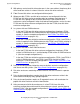
Example IOAM and Disk Drive Enclosure
Configurations
Daisy-Chain Configurations
When planning for possible use of daisy-chained disks, consider:
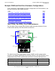
This illustration shows an example of Fibre Channel cable connections between the
two FCSAs and four disk drive enclosures in a single daisy-chain configuration.
$AUDIT (mirror) 110.2.1.2 and 111.2.1.2 110.212.103
$OSS (mirror) 110.2.1.2 and 111.2.1.2 110.212.104
*
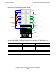
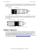
For an illustration of the disk drive enclosure factory-default slot locations, see Factory-
Default Disk Volume Locations on page 4-21
Daisy-Chained Disks
Recommended for ...
Daisy-Chained Disks Not
Recommended for ...
Requirements for
Daisy-Chain
1
Cost-sensitive storage and
applications using low-
bandwidth disk I/O
Many volumes in a large Fiber
Channel loop. The more
volumes that exist in a larger
loop, the higher the potential
for negative impact from a
failure that takes down a Fiber
Channel loop.
All daisy-chained disk drive
enclosures reside in the
same cabinet and are
physically grouped together.
Where low-cost,
high-capacity data storage
is important.
Applications with a highly
mixed workload, such as
transaction data bases or
applications with high disk I/O.
ID expander harness with
terminators are installed for
proper disk drive enclosure
and drive identification.
FCSA for each Fibre
Channel loop installs in a
different IOAM module for
fault tolerance.
Two disk drive enclosures
minimum, with four disk
drive enclosures maximum
per daisy-chain.
1
See
Fibre Channel Devices on page 4-19.
Disk Volume Name FCSA GMSP Disk GMES
*