
NonStop NS-Series Planning Guide (H06.03+)


Planning for LAN Communications
HP Integrity NonStop NS-Series Planning Guide—529567-004
6-3
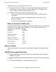
IP Addresses
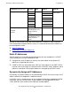
This illustration shows a fault-tolerant LAN configuration with two maintenance
switches:
IP Addresses
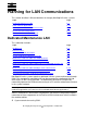
Servers require IP addresses for these components that are connected to the LAN:
•
P-switch ServerNet switch boards
•
IOAM enclosure ServerNet switch boards
•
Maintenance switch
•
System consoles
•
OSM Low-Level Link
•
OSM Service Connection
•
UPS (optional)
VST072.vsd
Maintenance
Switch 1
Operations LAN
Backup System
Console
Modem
Primary System
Console
IOAM Enclosure
Maintenance
Switch 2
10/100 ENET
Port, ServerNet
Switch Boards
Modem
DHCP
DNS
server
(optional)
Processor
Switch
X ServerNet
Maintenance
PIC - ENet (Slot
1, Port 3)
11 1310 12
3
2
1
4
3
2
1
4
3
2
1
4
3
2
1
3
2
1
4
3
2
1
4
3
2
1
4
3
2
1
4
123456789
Processor
Switch
Y S e rve rNet
11 1310 12
3
2
1
4
3
2
1
4
3
2
1
4
3
2
1
3
2
1
4
3
2
1
4
3
2
1
4
3
2
1
4
123456789
G4SA
(Y Fabric)
Module 3,
Slot 5, Port A
G4SA
(X Fa bri c)
Module 2,
Slot 5, Port A
UPS (optional)
G4SA
G4SA
G4SA
G4SA
FCSA
FCSA
FCSA
FCSA
FCSA
FCSA
Optional
Connecti on to
Operations
LAN (One or
Two
Connections)
ServerNet
Switch Board
Module 2
ServerNet
Switch Board
Module 3
Remote Service
Provider
Remote Service
Provider