
NonStop NS-Series Planning Guide (H06.03+)


HP Integrity NonStop NS-Series Planning Guide—529567-004
B-1
B
Example Modular Configurations
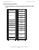
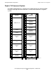
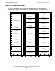
This appendix shows example configurations of the Integrity NonStop NS-series
modular hardware that can be installed in a cabinet. A number of other configurations
are also possible because of the flexibly inherent to the NonStop advanced
architecture and ServerNet, and the number of cabinets in a system.
Topics include:
Minimum, Typical, and Maximum Hardware
Configuration
This table shows the minimum, typical, and maximum number of the modular
components installed in a system. These typical values might not reflect the system
you are planning and are provided only as an example, not as exact values.
Note. Hardware configuration drawings in this appendix represent the physical arrangement of
the modular enclosures, but do not show location of the PDU junction boxes. Location of the
PDU junction boxes are optional for AC power feed from above or below the cabinet.
Topic Page
Minimum, Typical, and Maximum Hardware Configuration
B-1
Typical Configurations B-2
Other Configurations B-12
Example Internal Cabling B-21
Enclosure or
Component
(page 1 of 2)
Duplex Processor Triplex Processor
Minimum Typical Maximum Minimum Typical Maximum
4-Processor slice
with 16 DIMMs
248 3 612
4-GB memory
quad
4 16 32 6 24 48
Processor board
with 2 1.6 GHz
processors
2-- 3 --
Processor board
with 4 1.6 GHz
processors
-48 - 612
LSU logic board
and optics adapter
288 2 88
P-switch 2 2 2 2 2 2
IOAM enclosure 1 2 6 1 2 6