
NonStop NS-Series Planning Guide (H06.03+)


Example Modular Configurations
HP Integrity NonStop NS-Series Planning Guide—529567-004
B-2
Typical Configurations
Typical Configurations
This subsection shows the U locations of the modular hardware installed typical
configurations. These options can be installed in locations marked “Available Space” in
the configuration drawings:
•
Maintenance switch: 1U required
•
Tape converter (NonStop S-series connect: 1U required
•
Fibre connect tape with ACL: 5U required
•
Console: 2U required with recommended installation at cabinet offset 20U
•
Disk drive enclosure; installed in pairs; also called Fibre Channel Disk Module
(FCDM): 3U required each disk drive enclosure
Topics covered are:
FCSA 2 Up to
20 in
mixture
determi
ned by
disks
and I/O
Up to 60 in
mixture
determined
by disks
and I/O
2Up to
20 in
mixture
determi
ned by
disks
and I/O
Up to 60 in
mixture
determined
by disks
and I/O
G4SA 2 2
Disk drive
enclosure (Fibre
Channel disk
module)
248 2 48
Fibre Channel disk
drives
14561121456112
Topic Page
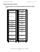
Duplex 4-Processor System
B-3
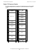
Duplex 8-Processor System B-4
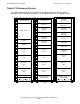
Duplex 12-Processor System B-5
Duplex 16-Processor System, Three Cabinets B-6
Duplex 16-Processor System, Two Cabinets B-7
Triplex 4-Processor System B-8
Triplex 8-Processor System B-9
Triplex 12-Processor System B-10
Triplex 16-Processor System, Three Cabinets B-11
Enclosure or
Component
(page 2 of 2)
Duplex Processor Triplex Processor
Minimum Typical Maximum Minimum Typical Maximum