
NonStop NS-Series Planning Guide (H06.03+)
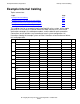


Example Modular Configurations
HP Integrity NonStop NS-Series Planning Guide—529567-004
B-24
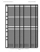
Example Internal Cabling
This illustration shows the U location of the modular enclosures listed in the preceding
table:
For a simplified illustration of the ServerNet cabling for this example system, see
Example 4-Processor Duplex System Cabling on page B-25.
For details and instructions on connecting cables as part of the system installation,
refer to the NonStop NS-Series Hardware Installation Manual.
38
39
40
41
42
33
34
35
36
37
28
29
30
31
32
23
24
25
26
27
18
19
20
21
22
13
14
15
16
17
08
09
10
11
12
03
04
05
06
07
01
02
38
39
40
41
42
33
34
35
36
37
28
29
30
31
32
13
14
15
16
17
08
09
10
11
12
03
04
05
06
07
01
02
23
24
25
26
27
18
19
20
21
22
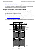
IOAM Enclosure
(U23)
Maintenance
Switch (U1)
To AC Power Source or Site UPS
ServerNet
Adapters
Slice A (U3)
Slice B (U8)
LSU Enclosure (U13)
P-Switch X (U17)
P-Switch Y (U20)
VST422.vsd
Primary DDE (U37)
Mirror DDE (U34)
Fibre Channel-SCSI
Converter (U40)