
NonStop NS-Series Planning Guide (H06.03+)
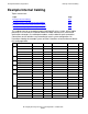


Example Modular Configurations
HP Integrity NonStop NS-Series Planning Guide—529567-004
B-25
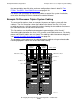
Example 4-Processor Duplex System Cabling
Example 4-Processor Duplex System Cabling
This illustration shows example 4-processor duplex system in a single cabinet. This is
a simplified and conceptual representation of the X and Y ServerNet cabling between
the slice, LSU, p-switch, and IOAM enclosures. For clarity, power and Ethernet cables
are not shown. For cable-by-cable interconnect diagrams, see Internal ServerNet
Interconnect Cabling on page 4-4.
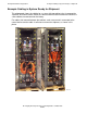
Cable management hardware that is part of each modular enclosure as well as on the
rack is not shown. Therefore, actual cable routing using the cable management
hardware is different from that shown. For detailed information on cable routing, refer
to the Integrity NonStop NS-Series Hardware Installation Manual.
This illustration also shows an example of the modular I/O hardware with simplified
representation of the X and Y ServerNet cabling between the IOAM enclosures and the
p-switches and the simplified Fibre Channel cabling between the FCSAs and disk drive
enclosures. The example disk drive enclosure configuration for the group 110 IOAM is
VST.703.vsd
DDE M1
DDE P1
IOAM
110.3
IOAM
110.2
Slice 1A
Slice 1B
LSU
X
P-Switch
Y
P-Switch