
NonStop NS-Series Planning Guide (H06.03+)


Modular System Hardware
HP Integrity NonStop NS-Series Planning Guide—529567-004
2-10
Processor Slice
ID, such as A1, A2, A3, and so forth. These IDs reference the appropriate slice for
proper connection of the optic cables.
The slice optic cables provide communications between each slice and the LSU as
well as between the LSU and the X-fabric and Y-fabric p-switch PICs. No requirement
exists to connect cables from a particular slice optic adapter on a slice to a physically
corresponding adapter on an LSU. However, to help reduce the complexity of cable
connections, HP recommends that you use a physically sequential order of slots for
optic cable connections on the LSU and do not randomly mix the LSU slots.
Cable connections to the LSU has no bearing on processor complex number, but HP
also recommends you connect slices A to the slice A connection on the LSU. Optic
cable connections to the p-switch PICs determine the identification numbers of each
processor complex. For more information, see ServerNet Communications Network on
page 3-1.
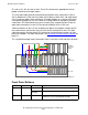
This simplified example shows connections from a slice to the LSU and to the p-switch:
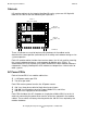
Front Panel Buttons
Button Function Condition Operation
Power Hard reset Power is on. Cycle power and reset or reconfigure logic.
Power in
standby.
Remain in standby.
TOC/NMI Soft reset Power is on. Send initialize interrupt to processors, but
without reset or reconfiguration of logic.
Slice 1A
LSU
Enclosure
20 272625242322
11 1310 12
B
A
X
C
B
A
X
C
B
A
Y
X
C
B
A
X
C
3
2
1
4
J1 J3 J5 J7 K1 K3 K5 K7
J0 J2 J4 J6 K0 K2 K4 K6
X-Fabric
Processor
Switch
VST206.vsd
Y
Y
21
Y
To Y-Fabric Processor Switch