
NonStop NS-Series Planning Guide (H06.03+)


Modular System Hardware
HP Integrity NonStop NS-Series Planning Guide—529567-004
2-12
Logical Synchronization Unit (LSU)
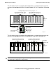
This illustration shows an example LSU configuration as viewed from the rear of the
enclosure and equipped with four LSU optics adapter PICs in I/O positions 20 through
23:
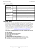
This illustration shows an example LSU configuration as viewed from the front of the
enclosure and equipped with four LSU logic boards in positions 20 through 23:
Caution. To maintain proper cooling air flow, blank panels must be installed in all slots that do
not contain logic adapter PICs or logic boards.
LSU
Enclosure
(back)
VST208.vsd
J set in I/O positions 20 - 23 for
logical processors 0 through 7
K set in I/O positions 24 - 27 for
logical processors 8 through 15
LSU Optic
Adapter PIC
B
A
Y
X
C
B
A
Y
X
C
B
A
Y
X
C
B
A
Y
X
C
20 27262524232221
B
A
Y
X
C
LSU Optic Adapter PICs Positions (Slots) 20 - 27
Green LED
(power)
Amber LED
(reset, fault)
Green LEDs
(link status)
LSU
Enclosure
(front)
VST209.vsd
2027 26 25 24 23 22 21
K set in LSU positions 24-27 for
logical processors 8 through 15
J set in LSU positions 20-23 for
logical processors 0 through 7
LSU Logic Board Positions (Slots) 20 - 27
Green LED
Amber LED