
NonStop NS-Series Planning Guide (H06.03+)


Modular System Hardware
HP Integrity NonStop NS-Series Planning Guide—529567-004
2-13
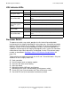
LSU Indicator LEDs
LSU Indicator LEDs
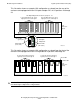
Processor Switch
The processor switch, or p-switch, provides the first level of ServerNet fabric
interconnect for the Integrity NonStop NS-series processors. ServerNet connection
from the LSU also defines the ID numbers, 0 through 15, for the logical processors
within the system. In cases where NonStop S-series I/O enclosures provide I/O
capabilities and storage for the Integrity NonStop NS-series system, the ServerNet
connection to the p-switch determines the NonStop S-series I/O enclosure group
number, as described in NonStop S-Series I/O Enclosure Group Numbers on
page 2-36.
Two p-switches are required, one each for the X and Y ServerNet fabrics. Physical
attributes for the 3U-high p-switch are:
•
Rack mountable
•
Dual AC power feeds and power supplies
•
Dual fans with front to rear cooling
•
Main logic board
•
Maintenance entity (ME) logic and firmware
•
Maintenance PIC (slot 1) for connection to maintenance switch
•
Cluster PIC (slot 2) for connection to 6770 or 6780 cluster switch
•
Crosslink PIC (slot 3) for connection to the other p-switch
LED State Meaning
LSU Optic Adapter
PIC (green LED)
Green Power is on; LSU is available for normal operation.
Off Power is off.
LSU Optic Adapter
PIC (amber LED)
Amber Power is in progress, board is being reset, or a fault
exists.
Off Normal operation or powered off.
LSU Optic Adapter
connectors (green
LEDs)
Green Slice optic or ServerNet link is functional.
Off Power is off, or a fault exists (amber LED is on).
LSU Logic Board
(green LED)
Green Power is on with LSU available for normal operation.
Off Power is off.
LSU Logic Board
PIC (amber LED)
Amber Power is in progress, board is being reset, or a fault
exists.
Off Normal operation or powered off.