
NonStop NS-Series Planning Guide (H06.03+)


Modular System Hardware
HP Integrity NonStop NS-Series Planning Guide—529567-004
2-14
Processor Switch
•
ServerNet I/O PICs (slots 4 to 9); provide 24 ServerNet 3 connections to one or
more IOAMs and to optional NonStop S-series I/O enclosures
•
Processor I/O PICs (slots 10 to 13); connect to LSU for ServerNet 3 I/O with the
processors
•
Cable management and connectivity on the rear of the cabinet
P-switch FRUs include
•
ServerNet switch board
•
Quad MMF PIC (up to 10) for processor connection to LSUs and I/O connections
to IOAM enclosures, NonStop S-series I/O enclosures, and ServerNet cluster
switch (model 6780)
•
SMF PIC for connection to ServerNet cluster switch (model 6770)
•
Cross-link PIC for crossover connections between the two p-switches in the
system
•
Maintenance PIC for Ethernet connection to the maintenance switch and for SPON
connection to a NonStop S-series I/O enclosure.
•
Power supplies (2)
•
Fans (2)
Each p-switch is the ServerNet fabric (X or Y) hub for all local and remote ServerNet
connections. Functions of the p-switch include:
•
ServerNet interconnect between processors
•
ServerNet interconnect between processors and IOAM
•
ServerNet interconnect between processors and IOMF 2 for NonStop S-series I/O
•
Interface for LAN and system maintenance for:
°
Processor control
°
Environmental sense and control (ESC)
°
Coldload of TACL and EMS windows
°
ServerNet configuration
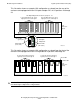
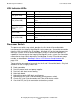
This illustration shows the front of the p-switch:
The display is a 20-character by 2-line liquid crystal display (LCD) for configuration
information:
Caution. To maintain proper cooling air flow, blank panels must be installed in all slots that do
not contain PICs.
VST402.vsd
PWR
PWR
FAN
FAN
DISPLAY
SPON
100/10 ENET 1 2 3 4