
NonStop NS-Series Planning Guide (H06.03+)


Modular System Hardware
HP Integrity NonStop NS-Series Planning Guide—529567-004
2-15
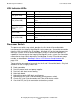
P-Switch Indicator LEDs
•
IP address
•
Group-module-slot
•
Cabinet name and offset
•
ME firmware revision
•
Floating point gate array (FPGA) firmware revision
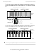
This illustration shows the rear of a fully populated p-switch:
P-Switch Indicator LEDs
Processor Numbering
Connection of the ServerNet cables from the LSU to the PICs in p-switch slots 10
through 13 determines the number of the associated logical processor. For more
information, see LSUs to Processor Switches and Processor IDs on page 4-8.
LED State Meaning
All PICs Green Power is on with PIC available for normal operation.
Off Power is off.
Amber A fault exists.
Off Normal operation or powered off.
PIC ServerNet
connector (green
LED)
Green ServerNet link is functional.
Off ServerNet link is not functional.
Display Messages Status messages are displayed.
VST500.vsd
Maintenance PIC
Cluster PIC
Crosslink PIC
I/O PICs
Processor PICs
1
2
3
4
1
2
3
4
1
2
3
4
1
2
3
4
1
2
3
4
1
2
3
4
1
2
3
4
1
2
3
4
1
2
3
4
1
2
3
4
1
2
3
4
1
2
3
4
1
2
3
EFT
Slots 1
13
2 3 4 5 6 7 8
1211109