
NonStop NS-Series Planning Guide (H06.03+)


Modular System Hardware
HP Integrity NonStop NS-Series Planning Guide—529567-004
2-16
Processor Numbering
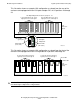
This example of a triplex processor shows the ServerNet cabling to the p-switch PIC in
slot 10 that defines processors 0, 1, 2, and 3. This configuration is only an example to
be used for understanding the interconnection.
Slice 1C
(not use in
duplex
system)
Slice 1A
Slice 1B
LSU
Enclosure 0
20 272625242322
1 2 3 4 5 6 7 8
1 2 3 4 5 6 7 8
1 2 3 4 5 6 7 8
11 1310 12
B
A
X
C
B
A
X
C
B
A
Y
X
C
B
A
X
C
3
2
1
4
J1 J3 J5 J7 K1 K3 K5 K7
J0 J2 J4 J6 K0 K2 K4 K6
J1 J3 J5 J7 K1 K3 K5 K7
J0 J2 J4 J6 K0 K2 K4 K6
J1 J3 J5 J7 K1 K3 K5 K7
J0 J2 J4 J6 K0 K2 K4 K6
X Fabric
Processor
Switch
P-switch slot 10, port 1: Processor 0
P-switch slot 10, port 2: Processor 1
P-switch slot 10, port 3: Processor 2
P-switch slot 10, port 4: Processor 3
11 1310 12
Y Fabric
Processor
Switch
3
2
1
4
VST210.vsd
Y
Y
21
Y
S T Q R
S T Q R
S T Q R