
NonStop NS-Series Planning Guide (H06.03+)


Modular System Hardware
HP Integrity NonStop NS-Series Planning Guide—529567-004
2-29
Rack and Offset Physical Location
In NonStop S-series systems, group, module, and slot (GMS) notation identifies the
physical location of a component. However, GMS notation in Integrity NonStop
NS-series systems is the logical location of particular components rather than the
physical location.
Rack and Offset Physical Location
Rack name and rack offset identify the physical location of components in an Integrity
NonStop NS-series system. The rack name is located on an external label affixed to
the rack, which includes the system name plus a 2-digit rack number.
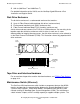
Rack offset is labeled on the rails in each side of the rack. These rails are measured
vertically in units called U, with one U measuring 1.75 inches (44 millimeters). The rack
is 42U high with 1U located at the bottom and 42U at the top. The rack offset is the
lowest number on the rack that the component occupies.
This example shows the location of slice A in rack 1 with an offset of 3U and slice B
with an offset of 8U:
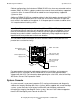
Slice Group-Module-Slot Numbering
•
Processor group: 400-403 relates to processor complex of 0-3
Example: group 403 = processor complex 3
•
Module: 1-3 relates to the CPU slice ID of A-C
Example: module 2 = slice B
•
Slot: 71-78 relates to location of the slice optics adapter
Example: Slot 72 = optics adapter in slot 72
•
Port: J0-J7 or K0-K7 relates to the two optic ports in a specific slot
VST404.vsd
08
09
10
11
03
04
05
06
07
01
02
08
09
10
11
03
04
05
06
07
01
02
Rack 1
(first 10 U shown)
Slice B
(offset 8U)
Slice A
(offset 3U)