
NonStop NS-Series Planning Guide (H06.03+)


Modular System Hardware
HP Integrity NonStop NS-Series Planning Guide—529567-004
2-31
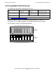
LSU Group-Module-Slot Numbering
LSU Group-Module-Slot Numbering
This table shows the default numbering for the LSUs:
Group and module numbers correspond to the logical processor number (0, 1, 2, 3)
and slice (A, B, C) as determined by the ServerNet connection to the p-switch.
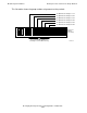
This illustrations shows the LSU position locations:
Item
Group (Processor
Complex)
1
Module I/O Position (Slot)
Individual LSU J set 400-403 100 + processor
complex number
1 - LSU optics adapter
2 - LSU logic board
Individual LSU K set Not used at this time
1
See Slice Group-Module-Slot Numbering on page 2-29.
VST215.vsd
LSU
Enclosure
(front)
LSU Logic Board Positions (Slots) 27-20
2027 26 25 24 23 22 21
LSU
Enclosure
(rear)
20 27262524232221
B
A
Y
X
C
B
A
Y
X
C
B
A
Y
X
C
B
A
Y
X
C
LSU Logic Board Positions (Slots) 20-27