
NonStop NS-Series Planning Guide (H06.03+)


System Configurations
HP Integrity NonStop NS-Series Planning Guide—529567-004
4-8
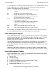
Processor Slice to Processor Slice
Processor Slice to Processor Slice
Reintegration cables interconnect each of the slices within individual duplex or triplex
processor complexes using connectors S, T, Q, and R as shown in the illustrations on
the next four pages.
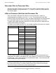
LSUs to Processor Switches and Processor IDs
Each slice contains four processor elements, and each element is a part of a
numbered processor complex, such as 0, 1, 2, or 3. The maintenance entity (ME)
firmware running in the p-switches assigns a number to each processor element based
on its connection from the LSUs to ServerNet via the p-switch ports in slots 10-13.
Therefore, optic cable connections from the LSUs to the p-switch PICs determine the
number of each processor complex.
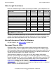
This table lists the default p-switch PIC slot and port coupling to the processor number.
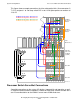
The four cabling diagrams on the next pages illustrate the default configuration and
connections for a triplex system processor. These diagrams are not for use in installing
or cabling the system. For instructions on connecting the cables, see the NonStop NS-
Series Hardware Installation Manual.
P-Switch PIC Slot PIC Port Processor Number
10 1 0
21
32
43
11 1 4
25
36
47
12 1 8
29
310
411
13 1 12
213
314
415
Note. Individual slice enclosures might or might not reside in the same cabinet, depending on
the physical configuration of the system. But regardless of which cabinet houses the slice,
LSU, and p-switch enclosures, the default cable interconnections between them will be the
same as the examples shown in the next four cabling diagrams.