
NonStop NS-Series Planning Guide (H06.03+)


System Configurations
HP Integrity NonStop NS-Series Planning Guide—529567-004
4-11
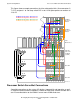
LSUs to Processor Switches and Processor IDs
This figure shows example connections of the slice reintegration links (slice connectors
S, T, Q, R) and ports 1 to 4 of the p-switch PIC in slot 12 for triplex processor numbers
to 8 to 11:
20 27262524232221
1 2 3 4 5 6 7 8
1 2 3 4 5 6 7 8
1 2 3 4 5 6 7 8
J1 J3 J5 J7 K1 K3 K5 K7
J0 J2 J4 J6 K0 K2 K4 K6
J1 J3 J5 J7 K1 K3 K5 K7
J0 J2 J4 J6 K0 K2 K4 K6
J1 J3 J5 J7 K1 K3 K5 K7
J0 J2 J4 J6 K0 K2 K4 K6
X-Fabric
Processor
Switch
11 1310 12
1
2
3
4
Slice 3C
(not used
in duplex
system)
Slice 3A
Slice 3B
LSU
Enclosure 1
Y-Fabric
Processor
Switch
11 1310 12
4
3
1
2
B
A
Y
X
C
B
A
Y
X
C
B
A
Y
X
C
B
A
Y
X
C
S T Q R
S T Q R
S T Q R
VST212.vsd
P-switch slot 12, port 1: Processor 8
P-switch slot 12, port 2: Processor 9
P-switch slot 12, port 3: Processor 10
P-switch slot 12, port 4: Processor 11