
NonStop NS-Series Planning Guide (H06.03+)


System Configurations
HP Integrity NonStop NS-Series Planning Guide—529567-004
4-18
Software and Migration Requirements
°
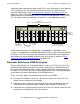
A serial cable from each SPON connector on the p-switch carries power-on
signals to the NonStop S-series I/O enclosure. This cable is a unidirectional
SPON cable used only for connection between an Integrity NonStop NS-series
system p-switch and the IOMF 2 CRU in the NonStop S-series I/O enclosure.
°
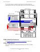
If the system has no IOAM enclosures and you want system communications
with the OSM Service Connection and OSM Notification Director, the NonStop
S-series I/O enclosure must provide connection for the maintenance LAN via
two category 5 Ethernet cables.
Software and Migration Requirements
•
Configure I/O PICs on the p-switch to accept the NonStop I/O connections using
the OSM Low-Level Link after the system is powered on but before it is started, as
described in the Integrity NonStop NS-Series Hardware Installation Manual.
•
To perform a system load of the Integrity NonStop NS-series server using the
NonStop S-series I/O enclosure, the $SYSTEM disk must reside in group 11,
module 1, slot 11 and must contain the H03 operating system files.
•
SQL/MP objects that are present on disks installed in a NonStop S-series I/O
enclosure are not immediately usable after connecting the enclosure to an Integrity
NonStop NS-Series system. The file labels and catalogs must be updated to reflect
the new system name and number. The SQLCI MODIFY command can be used to
update SQL/MP objects, as described in the migration information contained in the
SQL Supplement for H-Series RVUs.
•
G-series application programs that reside on a NonStop S-series I/O enclosure
might require migration changes to run on an Integrity NonStop NS-series system
H-series RVU. For more information, refer to the H-Series Application Migration
Guide.