
NonStop NS-Series Planning Guide (H06.03+)


System Configurations
HP Integrity NonStop NS-Series Planning Guide—529567-004
4-21
Factory-Default Disk Volume Locations
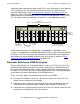
Disk drive enclosures connect to Fibre Channel ServerNet adapters (FCSAs) via Fiber
Channel arbitrated loop cables. This drawing shows the two Fibre Channel arbitrated
loops implemented within the disk drive enclosure.
For more information on the disk drive enclosure, see Disk Drive Enclosure on
page 2-21.
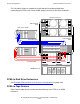
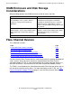
Factory-Default Disk Volume Locations
This illustration shows the factory-default locations for the primary and mirror system
disk volumes where they reside in separate disk drive enclosures:
FCSA location and Fibre Channel cable connections vary according to the various
controller and disk drive enclosure combinations.
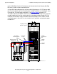
Fibre Channel Device Configurations
Storage subsystems in NonStop S-series systems used a fixed hardware layout. Each
enclosure can have up to four controllers for storage devices and up to 16 internal disk
drives. The controllers and disk drives always have a fixed logical location with
standardized location IDs of group-module-slot. Only the group number changes as
determined by the enclosure position in the ServerNet topology.
However, the modular Integrity NonStop NS-series systems have no fixed boundaries
for the hardware layout. Up to 60 FCSA (or 120 ServerNet addressable controllers)
and 240 Fiber Channel disk enclosures are possible with identification depending on
the ServerNet connection of the IOAM and slot housing in the FCSAs.
FC AL Port A2
(at rear of
enclosure)
FC AL Port B2
(at rear of
enclosure)
VSD.501.vst
Disk Drive Enclosure
(front)
FC AL Port B1
(at rear of
enclosure)
FC AL Port A1
(at rear of
enclosure)
Fi bre Channel
Arbitra ted Lo op B
Fi bre Channel
Arbitrated Loop A
Disk Drive
Enclosure
(front)
VSD.082.vst
$SYSTEM (slot 1)
$DSMSCM (slot 2)
$AUDIT (slot 3)
$OSS (slot 4)