
NonStop NS-Series Planning Guide (H06.05+)


Modular System Hardware
HP Integrity NonStop NS-Series Planning Guide—529567-008
5-33
LSU Group-Module-Slot Numbering
LSU Group-Module-Slot Numbering
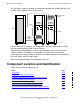
This table shows the default numbering for the LSUs:
Group and module numbers correspond to the logical processor number (0, 1, 2, 3)
and NonStop Blade Element (A, B, C) as determined by the ServerNet connection to
the p-switch.
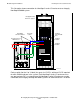
This illustration shows an example LSU configuration equipped with four optic adapters
(rear side) in slots 20 through 23, and four LSU logic boards (front side) in positions 50
through 53:
Item
Group (NonStop
Blade Complex)
1
Module I/O Position (Slot)
Individual LSU J set 400-403 100 + NonStop
Blade Complex
number
1 - Optic Adapter (rear side,
slots 20-27)
2 - Logic Board (front side,
slots 50-57)
Individual LSU K set Not used at this time
1
See NonStop Blade Element Group-Module-Slot Numbering on page 5-32.
VST215.vsd
LSU
Enclosure
(front)
LSU Logic Board Positions (Slots) 50-57
5057 56 55 54 53 52 51
LSU
Enclosure
(rear)
20 27262524232221
B
A
Y
X
C
B
A
Y
X
C
B
A
Y
X
C
B
A
Y
X
C
LSU Logic Board Positions (Slots) 20-27