
NonStop NS-Series Planning Guide (H06.05+)


Modular System Hardware
HP Integrity NonStop NS-Series Planning Guide—529567-008
5-34
Processor Switch Group-Module-Slot Numbering
Processor Switch Group-Module-Slot Numbering
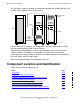
This table shows the default numbering for the p-switch:
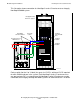
This illustration shows the slot and connector locations for the p-switch:
Group
X ServerNet
Module
Y ServerNet
Module Slot Item
100 2 3 1 Maintenance PIC
2 Cluster PIC
3 Crosslink PIC
4 - 9 ServerNet I/O PICs
10 ServerNet PIC (processors 0-3)
11 ServerNet PIC (processors 4-7)
12 ServerNet PIC (processors 8-11)
13 ServerNet PIC (processors 12-16)
14 P-switch logic board
15, 18 Power supply A and B
16, 17 Fan A and B
Processor
Switch
(rear view)
11 1310 12
3
2
1
4
3
2
1
4
3
2
1
4
3
ENET
2
SPON
1
SER
3
2
1
4
3
2
1
4
3
2
1
4
3
2
1
4
123456789
VST506.vsd
Maintenance
PIC
Cluster
PIC
Crosslink
PIC
ServerNet PICs
System I/O Slots
(to IOAM, NonStop S-series I/O
enclosure)
Processor I/O Slots
(to processors via LSU)
Processor
Switch
(front view)
PWR
PWR
FAN
FAN
DISPLAY
SPON 100/10 ENET 1
234