
NonStop NS-Series Planning Guide (H06.05+)


System Configuration Guidelines
HP Integrity NonStop NS-Series Planning Guide—529567-008
6-22
Fibre Channel Devices
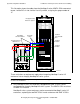
This illustration shows the locations of the hardware in the Fibre Channel disk module
as well as the Fibre Channel port connectors at the back of the enclosure:
Fibre Channel disk modules connect to Fibre Channel ServerNet adapters (FCSAs) via
Fiber Channel arbitrated loop (FC-AL) cables. This drawing shows the two Fibre
Channel arbitrated loops implemented within the Fibre Channel disk module.
For more information on the Fibre Channel disk module, see Fibre Channel Disk
Module on page 5-25.
FC-AL
Port A2
Port A1
FC-AL
Port B2
Port B1
Fibre
Channel
Disk Module
(rear)
VSD.503.vst
Fibre
Channel
Disk Module
(front)
Disk Drive Bays 1-14
EMU
FC -A L P ort A 2
(at rear of
module)
FC-AL Port B2
(at rear of
module)
VSD.501.vst
Fibre Channel Disk Module
(front)
FC -AL Port B1
(at rear of
module)
FC -A L P ort A 1
(at rear of
module)
Fi bre Channel
Arbitra ted Lo op B
Fi bre Channel
Arbitrated Loop A