
NonStop NS-Series Planning Guide (H06.05+)


System Configuration Guidelines
HP Integrity NonStop NS-Series Planning Guide—529567-008
6-32
Example Configurations of the IOAM Enclosure and
Fibre Channel Disk Module
This illustration shows an example of cable connections between the two FCSAs and
four Fibre Channel disk modules in a single daisy-chain configuration.
A second equivalent configuration, including an IOAM enclosure, two FCSAs, four
Fibre Channel disk modules with ID expander, is required for fault-tolerant mirrored
disk storage. Installing each mirrored disk in the same corresponding FCDM and bay
number as its primary disk in not required, but it is recommend to simplify the physical
management and identification of the disks.
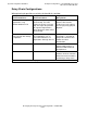
This table list the FCSA group-module-slot-port (GMSP) and disk
group-module-shelf-bay (GMSB) identification for the factory-default system disk
locations in a daisy-chained configuration:
Disk Volume Name FCSA GMSP Disk GMSB
*
$SYSTEM 110.2.1.1 and 110.3.1.1 110.211.101
$DSMSCM 110.2.1.1 and 110.3.1.1 110.211.102
$AUDIT 110.2.1.1 and 110.3.1.1 110.211.103
$OSS 110.2.1.1 and 110.3.1.1 110.211.104
*
For an illustration of the Fibre Channel disk module factory-default slot locations, see
Factory-Default Disk Volume Locations on page 6-23.
IOAM
Enclosure
VST081.vsd
FCDM 2
FCDM 1
B Side A Side
FCSA
ID Expanders
FCDM 4
FCSA
FCDM 3
Terminator
Terminator
Fiber-Optic
Cables
Fibrer-Optic
Cables