HP Integrity NonStop NS1000 Planning Guide HP Part Number: 542527-010 Published: November 2009 Edition: H06.
© Copyright 2009 Hewlett-Packard Development Company, L.P. Legal Notice Confidential computer software. Valid license from HP required for possession, use or copying. Consistent with FAR 12.211 and 12.212, Commercial Computer Software, Computer Software Documentation, and Technical Data for Commercial Items are licensed to the U.S. Government under vendor’s standard commercial license. The information contained herein is subject to change without notice.
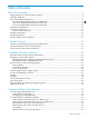
Table of Contents About This Document.........................................................................................................9 Supported Release Version Updates (RVUs)..........................................................................................9 Intended Audience.................................................................................................................................9 New and Changed Information.............................................................
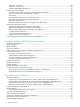
Enclosure AC Input.........................................................................................................................28 Enclosure Power Loads...................................................................................................................28 Model R5500 XR Integrated UPS.....................................................................................................29 Dimensions and Weights............................................................................
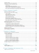
System Console.....................................................................................................................................64 Enterprise Storage System (Optional)..................................................................................................64 Component Location and Identification...............................................................................................65 Terminology...............................................................................
System Console...................................................................................................................................109 System Console Configurations....................................................................................................110 Maintenance Architecture...................................................................................................................112 Dedicated Service LAN..................................................................
List of Figures 1-1 1-2 3-1 Integrity NonStop NS1000 Server Example..................................................................................16 Example of an Integrity NonStop NS1000 System........................................................................17 Example of a 4-Processor Configuration.......................................................................................
List of Tables 3-1 8 Example of Cabinet Load Calculations.........................................................................................
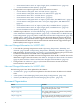
About This Document This guide describes the HP Integrity NonStop™ NS1000 system and provides examples of system configurations to assist you in planning for installation of a new system. Supported Release Version Updates (RVUs) This publication supports H06.08 and all subsequent H-series RVUs until otherwise indicated by its replacement publication. NOTE: For NonStop NS1000 servers that contain I/O Adapter Module (IOAM) enclosures, refer to the H06.
— — “International 200 to 240 V AC input, Single phase, 32A RMS Power” (page 52) “Power Distribution Units (PDUs)” (page 52) • Changed the C19 receptacle type from 12A to 16A in these sections: — “North America and Japan: 208 V AC PDU Power” (page 26) — “North America and Japan: 200 to 240 V AC PDU Power” (page 26) — “International: 380 to 415 V AC PDU Power” (page 27) — “International: 200 to 240 V AC PDU Power” (page 27) — “North America and Japan 208 V AC input, 3-phase delta, 24A RMS Power” (page 51)
Section Contents Chapter 4 (page 37) This chapter introduces the Integrity NonStop NS1000 system. Chapter 5 (page 49) This chapter includes topics to consider when you are planning or upgrading the installation site. Chapter 6 (page 75) This chapter describes the guidelines for implementing the modular hardware. Chapter 7 (page 93) This chapter shows example configurations of the Integrity NonStop NS1000 modular hardware.
[ ] Brackets Brackets enclose optional syntax items. For example: TERM [\system-name.]$terminal-name INT[ERRUPTS] A group of items enclosed in brackets is a list from which you can choose one item or none. The items in the list can be arranged either vertically, with aligned brackets on each side of the list, or horizontally, enclosed in a pair of brackets and separated by vertical lines.
Item Spacing Spaces shown between items are required unless one of the items is a punctuation symbol such as a parenthesis or a comma. For example: CALL STEPMOM ( process-id ) ; If there is no space between two items, spaces are not permitted. In this example, no spaces are permitted between the period and any other items: $process-name.
1 System Overview Overview of the Integrity NonStop NS1000 System The Integrity NonStop NS1000 system combines up to eight HP Integrity rx2620 servers with the NonStop operating system. Each HP Integrity rx2620 server contains a single Intel® Itanium® processor. The Integrity NonStop NS1000 server supports configurations of two, four, six, or eight processors. It uses much of the same modular system hardware as other Integrity NonStop NS-series servers.
Figure 1-1 Integrity NonStop NS1000 Server Example Hardware Enclosures and Configurations Enclosures that house specific hardware components in an Integrity NonStop NS1000 system include: • • • • • • Blade element (HP Integrity rx2620 server) Versatile I/O (VIO) enclosure Fibre Channel disk module (FCDM) Maintenance switch (Ethernet) Uninterruptible power supply (UPS) (optional) Extended runtime module (ERM) (optional) A large number of enclosure combinations is possible within the modular cabinets of an
Figure 1-2 Example of an Integrity NonStop NS1000 System Preparation for Other Server Hardware This guide provides the specifications only for the Integrity NonStop NS1000 server modular cabinets and enclosures identified earlier in this section. For site preparation specifications for other HP hardware that will be installed at the site with the Integrity NonStop NS1000 servers, consult with your HP account team.
2 Installation Facility Guidelines Modular Cabinet Power and I/O Cable Entry Power and I/O cables can enter the Integrity NonStop NS1000 server from either the top or the bottom rear of the modular cabinets, depending on how the cabinets are ordered from HP and the routing of the AC power feeds at the site. Integrity NonStop NS1000 server cabinets can be ordered with the AC power cords for the PDUs exiting either: • • Top: Power and I/O cables are routed from above the modular cabinet.
Power Quality This equipment is designed to operate reliably over a wide range of voltages and frequencies, described in “Enclosure AC Input” (page 28). However, damage can occur if these ranges are exceeded. Severe electrical disturbances can exceed the design specifications of the equipment.
For power information, refer to “Model R5500 XR Integrated UPS” (page 29). For complete information and specifications on the R5500 XR UPS, contact your HP representation or refer to the HP UPS R5500 XR Models User Guide available at: http://h10032.www1.hp.com/ctg/Manual/c00065453.
Weight Because modular cabinets for Integrity NonStop NS1000 servers house a unique combination of enclosures, total weight must be calculated based on what is in the specific cabinet, as described in “Modular Cabinet and Enclosure Weights With Worksheet” (page 32). Flooring Integrity NonStop NS1000 servers can be installed either on the site’s floor with the cables entering from above the equipment or on raised flooring with power and I/O cables entering from underneath.
but also all required personnel and lifting or moving devices. If necessary, enlarge or remove any obstructing doorway or wall. All modular cabinets have small casters to facilitate moving them on hard flooring from the unpacking area to the site. Because of these small casters, rolling modular cabinets along carpeted or tiled pathways might be difficult. If necessary, plan for a temporary hard floor covering in affected pathways for easier movement of the equipment.
3 System Installation Specifications This section provides specifications necessary for system installation site planning. NOTE: All specifications provided in this section assume that each enclosure in the modular cabinet is fully populated. The maximum current for each AC service depends on the number and type of enclosures installed in the modular cabinet.
feeds are routed at the site. Integrity NonStop NS1000 server cabinets can be ordered with the AC power cords for the PDU installed either: • • Top: Power and I/O cables are routed from above the modular cabinet. Bottom: Power and I/O cables are routed from below the modular cabinet NOTE: If your system includes the optional rackmounted HP R5500 XR UPS, the modular cabinet will have one PDU located on the rear left side and four extension bars on the rear right side.
International: 380 to 415 V AC PDU Power The PDU power characteristics are: PDU input characteristics • • • • 380 to 415 V ac, 3-phase Wye, 16A RMS, 5-wire 50/60Hz IEC309 5-pin, 16A input plug 6.
CAUTION: Be sure the hardware configuration and resultant power loads of each cabinet within the system do not exceed the capacity of the branch circuit according to applicable electrical codes and regulations. NOTE: If your system includes the optional rackmounted HP R5500 XR UPS, the modular cabinet will have one PDU located on the rear left side and four extension bars on the rear right side. To provide redundancy, components are plugged into the left-side PDU and the extension bars.
NOTE: If your system includes the optional rackmounted HP R5500 XR UPS, the modular cabinet will have one PDU located on the rear left side and four extension bars on the rear right side. To provide redundancy, components are plugged into the left-side PDU and the extension bars. Each extension bar is plugged into the UPS.
Dimensions and Weights This subsection provides information about the dimensions and weights for modular cabinets and enclosures installed in a modular cabinet and covers these topics: • • • • • • “Plan View From Above of the 36 and 42 U Modular Cabinets” (page 30) “Service Clearances for the Modular Cabinets” (page 30) “Unit Sizes” (page 30) “42U Modular Cabinet Physical Specifications” (page 31) “Enclosure Dimensions” (page 32) “Modular Cabinet and Enclosure Weights With Worksheet” (page 32) Plan View F
Enclosure Type Height (U) Extended runtime module 3 Rackmount console 2 36U Modular Cabinet Physical Specifications Item Height Width Depth Weight in. cm in. cm in. cm Modular cabinet 68.6 174.3 24.0 60.96 46.0 116.84 Rack 68.4 173.8 23.62 60.0 40.0 101.9 Front door 68.4 173.8 23.5 59.7 3.0 7.6 Left-rear door 68.4 173.8 11.0 27.9 1.0 2.5 Right-rear door 68.4 173.8 12.0 30.5 1.0 2.5 Shipping (palletized) 75.25 191.2 32.0 81.28 54.0 137.
Enclosure Dimensions EnclosureType Height in Width Depth cm in cm in cm Blade element 3.4 (rx2620) 8.6 19.0 48.2 26.8 68.0 VIO enclosure 6.9 17.5 19.0 48.3 27.0 68.6 Fibre Channel 5.2 disk module 13.1 19.9 50.5 17.6 44.8 Maintenance switch (Ethernet) 4.39 17.4 44.2 9.3 23.62 Rackmount 1.7 console system unitwith keyboard and display 4.3 16.8 42.7 24.0 60.9 1.7 4.3 15.6 39.6 17.0 43.2 R5500 XR UPS 5.1 13.0 17.5 44.5 26.0 66.0 Extended 5.
EnclosureType Number of Enclosures Weight Total lbs kg Extended runtime module (ERM) 170 77.1 Total -- -- 1 lbs kg Modular cabinet weight includes the PDUs and their associated wiring and receptacles. For examples of calculating the weight for various enclosure combinations, refer to “Calculating Specifications for Enclosure Combinations” (page 34).
Operating Temperature, Humidity, and Altitude Recommended Range1 Maximum Rate of Change per Hour Temperature (all except 41° to 95° F (5° to 35° C) Fibre Channel disk module) 68° to 77° F (20° to 25° C) 9° F (5° C) Repetitive 36° F (20° C) Nonrepetitive Temperature (Fibre Channel 50° to 95° F disk module) (10° to 35° C) - 1.8° F (1° C) Repetitive 5.
NOTE: If your system includes the optional rackmounted HP R5500 XR UPS, the modular cabinet will have one PDU located on the rear left side and four extension bars on the rear right side. To provide redundancy, components are plugged into the left-side PDU and the extension bars. Each extension bar is plugged into the UPS.
“Example of Cabinet Load Calculations” (page 36) lists the weight, power, and thermal calculations for the cabinet shown in “Example of a 4-Processor Configuration” (page 35). Table 3-1 Example of Cabinet Load Calculations 36 Component Quantity Height (U) Weight Volt-amps per AC feed Heat (BTU) (lbs) (kg) AC line(s) powered AC line(s) powered Single Both Single Both Blade element (rx2620) with 4 GB memory 4 8 224 100 880 1000 3004 3412 VIO enclosure 2 8 136 61.
4 Integrity NonStop NS1000 System Description This section describes the Integrity NonStop NS1000 system. For information about installing the Integrity NonStop NS1000 server hardware, refer to the NonStop NS1000 Hardware Installation Manual. NonStop Architecture The Integrity NonStop NS1000 server achieves full software fault tolerance by running the NonStop operating system on HP Integrity rx2620 servers.
In the event of a processor fault, the failed component within a blade element (fan or power supply) or the entire blade element can be replaced while the system continues to run. A single Integrity NonStop NS1000 system can have up to eight blade elements for a total of eight processors. Processors communicate with each other and with the system I/O over dual ServerNet fabrics. In the term ServerNet fabric, the word fabric is significant because it contrasts with the concept of a bus.
In summary, these terms describe specific components in the NonStop NS1000 system: Term Description Processor element (PE) A single microprocessor with its associated memory. In an Integrity NonStop NS1000 system: • A blade element contains one PE. • OSM uses the term logical processor to hierarchically reference a specific PE in a blade element. Blade element An HP Integrity rx2620 server that contains the PE, power supplies, fan assemblies, and firmware.
ServerNet Fabric I/O This subsection provides information about the ServerNet network in an Integrity NonStop NS1000 system and covers these topics: • • • • “Overview of the ServerNet Fabric” (page 40) “Simplified ServerNet System Diagram” (page 40) “ServerNet Pathways in the VIO Enclosure” (page 41) “Example of ServerNet Pathways” (page 42) For further information on the ServerNet network, protocols, IP addresses, and naming conventions, see the Introduction to Networking for Integrity NonStop NS-Series
ServerNet Pathways in the VIO Enclosure This drawing shows the ServerNet communication pathways in a pair of VIO enclosures. Optic lines connect the ServerNet PCI adapter cards in the blade elements with the ServerNet-to-processor ports in each VIO enclosure. The ServerNet-to-processor ports in VIO enclosure module 2 communicate with the X logic board. The ServerNet-to-processor ports in VIO enclosure module 3 communicate with the Y logic board.
Example of ServerNet Pathways This example shows the redundant routing and connection of the ServerNet X and Y fabric within a simple system. This example includes: • • 42 Four processors (0 through 3) contained in blade elements 1 through 4. Two VIO enclosures, group 100, connected to the ServerNet PCI adapter card in a blade element. For configurations of the VIO enclosures and Fibre Channel disk drives, see Chapter 6 (page 75).
If a cable, connection, router, or other failure occurs, only the system resources that are downstream of the failure on the same fabric are affected. Because of the redundant ServerNet architecture, communication takes the alternate path on the other fabric to the peer resources. For example, if the logic board for the Y fabric fails, the downstream adapters and the storage or communications that connect to the failed switch board are unavailable to the system through the Y fabric.
Modular Hardware Hardware for Integrity NonStop NS1000 systems is implemented in modules (enclosures installed in modular cabinets). For descriptions of the components and cabinets, see Chapter 5 (page 49). All Integrity NonStop NS1000 server components are field-replaceable units (FRUs) that can only be serviced by service providers trained by HP. For information about installing the Integrity NonStop NS1000 server hardware, refer to the NonStop NS1000 Hardware Installation Manual.
ALLPROCESSORS: SYSTEM_PROCESSOR_TYPE NOTE: NSE-P The OSM Service Connection displays the processor type as NSE-B.
The command interpreter input file (CIIN) is automatically invoked after the first processor is loaded. The CIIN file shipped with new systems contains the TACL RELOAD * command, which loads the remaining processors. For default configurations of the Fibre Channel ports, Fibre Channel disk modules, and load disks, see “Example Configurations of the VIO Enclosures and FCDMs” (page 85). For system load procedures, see the NonStop NS1000 Hardware Installation Manual.
• • Cabinet U location of the bottom edge of each enclosure Each ServerNet cable with: — Source and destination enclosure, component, and connector — Cable part number — Source and destination connection labels This document is called a tech memo and serves as the physical location and connection map for the system.
5 Modular System Hardware This section describes the hardware used in the Integrity NonStop NS1000 system. Several combinations of hardware component enclosures are possible within a modular cabinet for an Integrity NonStop NS1000 system. The applications and purpose of any Integrity NonStop NS1000 system determine the number and combination of hardware component enclosures within a cabinet.
Modular Cabinets The modular cabinet is a EIA standard 19-inch, 36 or 42 U, rack for mounting modular components. The modular cabinet comes equipped with front and rear doors and includes a rear extension that makes it deeper than some industry-standard racks. The “Power Distribution Units (PDUs)” (page 52) are mounted along the rear extension without occupying any U-space in the cabinet and are oriented inward, facing the components within the rack.
NOTE: If your system includes the optional rackmounted HP R5500 XR UPS, the modular cabinet will have one PDU located on the rear left side and four extension bars on the rear right side. To provide redundancy, components are plugged into the left-side PDU and the extension bars. Each extension bar is plugged into the UPS.
— — IEC309 5-pin, 16A input plug 6.
Each PDU in a modular cabinet has: • • • 36 AC receptacles per PDU (12 per segment) - IEC 320 C13 12A receptacle type 3 AC receptacles per PDU (1 per segment) - IEC 320 C19 16A receptacle type 3 circuit-breakers These PDU options are available to receive power from the site AC power source: • • • • 208 V ac, three-phase delta for North America and Japan 200 to 240 V ac, single phase for North America and Japan 380 to 415 V ac three-phase wye for International 200 to 240 V ac single phase for internationa
If your system includes the optional rackmounted HP R5500 XR UPS, the modular cabinet will have one PDU located on the rear left side and four extension bars on the rear right side. The PDU and extension bars are oriented inward, facing the components within the rack. To provide redundancy, components are plugged into the left-side PDU and the extension bars. Each extension bar is plugged into the UPS.
This illustration shows the AC power feed cables for the PDU and UPS for AC power feed from the bottom of the cabinet when the optional UPS and ERM are installed: Power Distribution Units (PDUs) 55
Each PDU is wired to distribute the load segments to its receptacles. CAUTION: If you are installing Integrity NonStop NS1000 system enclosures in a rack, balance the current load among the available load segments. Using only one of the available load segments, especially for larger systems, can cause unbalanced loading and might violate applicable electrical codes. Connecting the two power plugs from an enclosure to the same load segment causes failure of the hardware if that load segment fails.
HP Integrity rx2620 Server Description The HP Integrity rx2620 server is 2U and weighs 46 pounds (25 kilograms), is rackmountable, has redundant AC power feeds, and provides front-to-rear cooling. Each HP Integrity rx2620 server contains: Component Description One processor element (PE) A single 1.3 GHz 3 MB Intel Itanium microprocessor with its associated 4 GB or 8 GB memory. The memory is accessed from the top of the enclosure when the enclosure is pulled forward on its rails.
Component Description FRU Online/Offline* Power supplies Fans Blade element Memory upgrade Online Offline Offline Offline *Online means that the component can be replaced while the blade element is operational. Offline means that the blade element must be powered off before replacing the component.
This table describes front panel button and indicator LEDs for the preceding illustration: Front Panel Illustration Reference Number LED Indicator State Meaning 1 Locator LED and button On/Off The locator button and LED are used to help locate this server within a rack of servers.When the button is engaged, the blue LED illuminates and an additional blue LED on the rear panel of the server illuminates.
Front Panel Illustration Reference Number LED Indicator State Meaning 5 Power button On/Off This is the power on/off switch for the server. 6 Power LED On/Off The green on/off LED is illuminated when the power is on. ServerNet PCI Adapter Card Each HP Integrity rx2620 server contains one ServerNet PCI adapter card (installed in PCI slot 2) to provide ServerNet connectivity.
For each VIO enclosure to operate, at least one power supply in each VIO enclosure must be operational. For fault tolerance, you must connect the power supplies in each VIO enclosure to separate power distribution units (PDUs). For example, the power supplies located in slot 15 and slot 18 of each VIO enclosure cannot both be plugged into the left PDU.
you could configure these paths through the Fibre Channel ports located on the two VIO enclosures: Path Group Module Slot.Port Primary 100 02 1.1 Primary backup 100 03 1.1 Mirror 100 03 1.2 Mirror backup 100 02 1.2 These paths all exist within the same group. But they are divided between two VIO enclosures, so the configuration is fault-tolerant. For additional information, see “Fibre Channel Devices” (page 82).
HP NonStop Open System Management (OSM). For a general description of the maintenance switch, refer to the NonStop NS14000 Planning Guide. Details about the use or implementation of the maintenance switch that are specific to an Integrity NonStop NS1000 server are presented here.
NOTE: The AC input power cord for the R5500 XR UPS is routed to exit the modular cabinet at either the top or bottom rear corners of the cabinet, depending on what is ordered for the site power feed, and the large output receptacle is unused. For power and environmental requirements, planning, installation, and emergency power-off (EPO) instructions for the R5500 XR UPS, refer to the documentation shipped with the UPS.
Cables and switches vary, depending on whether the connection is direct, switched, or a combination: Connection LC-LC Cables Fibre Channel Switches Direct connect 2 Fibre Channel ports 0 Switched 4 Fibre Channel ports 1 or more Combination of direct and switched 2 Fibre Channel ports for each direct 1 connection4 Fibre Channel ports for each switched connection This illustration shows an example of connections between two VIO enclosures and an ESS via separate Fibre Channel switches: For fault to
Terminology These are terms used in locating and describing components: Term Definition Cabinet Computer system housing that includes a structure of external panels, front and rear doors, internal racking, and dual PDUs. Rack Structure integrated into the cabinet into which rackmountable components are assembled. Rack Offset The physical location of components installed in a modular cabinet, measured in U values numbered 1 to 42, with 1U at the bottom of the cabinet. A U is 1.
Rack offset is labeled on the rails in each side of the rack. These rails are measured vertically in units called U, with one U measuring 1.75 inches (44 millimeters). The rack is 36U with 1U located at the bottom and 36U at the top or 42U with 1U located at the bottom and 42U at the top. The rack offset is the lowest number on the rack that the component occupies.
NOTE: In OSM, if a blade element is not present or is powered off, processors might be renumbered. For example, if processor 3 has been removed, processor 4 becomes processor 3 in OSM displays.
This illustration shows the physical GMS numbering for the rear view of a blade element: This illustration shows the physical GMS numbering for the front and top view of a blade element: Component Location and Identification 69
Modular System Hardware
VIO Enclosure Group-Module-Slot Numbering An Integrity NonStop NS1000 system supports a single pair of VIO enclosures, identified as group 100: VIO Enclosure Group 100 Item Module Ports Slot X Fabric Y Fabric Displayed by OSM Displayed on Chassis 2 3 1 1 Fibre Channel 1 - 4 ports 2 2 Processor ports (processors 4-7) 3 3 Not supported 4 3 Not supported 5 5 Not supported 6 6a Ethernet ports C and D (optical) (10/100/1000 Mbps) 6 6b Ethernet ports A, B (10/100 (copper) Mbps) C, D
Modular System Hardware
Fibre Channel Disk Module Group-Module-Slot Numbering This table shows the default numbering for the Fibre Channel disk module: VIO Enclosure FCDM Group Module Slot Port Shelf Slot Item 100 2 - X fabric; 1 or 7c 1, 2 1 - 4 if daisy chained); 0 FCDM 1-14 Disk drives bays 89 Transceiver A1 90 Transceiver A2 91 Transceiver B1 92 Transceiver B2 93 Left FC_AL board 94 Right FC_AL board 95 Left power supply 96 Right power supply 97 Right blower 98 Left blower 99 EMU 3 - Y f
Modular System Hardware
6 System Configuration Guidelines This section provides configuration guidelines for an Integrity NonStop NS1000 system. Integrity NonStop NS1000 systems use a flexible modular architecture. Therefore, various configurations of the system’s modular components are possible within configuration restrictions stated in “Enclosure Locations in Cabinets” (page 76) and “VIO Enclosure and Disk Storage Considerations” (page 82).
Enclosure Locations in Cabinets This table provides details about the location of Integrity NonStop NS1000 server enclosures and components within a cabinet. The enclosure location refers to the U location on the rack where the lower edge of the enclosure resides, such as the bottom of an HP Integrity rx2620 server at 28U.
• • • • “Blade Element to VIO Enclosure” (page 79) “Processor ID Assignment for the Blade Element” (page 79) “Fibre Channel Ports to Fibre Channel Disk Modules” (page 81) “Fibre Channel Ports to Tape Devices” (page 82) For general information about internal ServerNet interconnect cabling, refer to the NonStop NS14000 Planning Guide. Details about internal ServerNet interconnect cabling specific to an Integrity NonStop NS1000 server are presented here.
nn.nn Identifies the slot location and port connection of the component. Near Refers to the information for this end of this cable. Far Refers to the information for the other end of this cable. When you replace a cable and either install or move an enclosure, be sure to update information on the labels at both ends of the cables.
Dedicated Service LAN Cables The Integrity NonStop NS1000 system also uses Category 5, unshielded twisted-pair Ethernet cables for the internal dedicated service LAN and for connections between the VIO enclosure and the application LAN equipment.
This table lists the default VIO enclosure slot and port coupling to the processor number: VIO Enclosure Module Slot.Port Fabric Processor Number Blade Number 2 14.1 X 0 1 14.2 X 1 2 14.3 X 2 3 14.4 X 3 4 2.1 X 4 5 2.2 X 5 6 2.3 X 6 7 2.4 X 7 8 14.1 Y 0 1 14.2 Y 1 2 14.3 Y 2 3 14.4 Y 3 4 2.1 Y 4 5 2.2 Y 5 6 2.3 Y 6 7 2.
Fibre Channel Ports to Fibre Channel Disk Modules Fibre Channel disk modules (FCDMs) can be connected directly to the Fibre Channel ports on a VIO enclosure (see “Blade Element to VIO Enclosure” (page 79)) with these exceptions: • • Only configurations with two VIO enclosures are supported.
Fibre Channel Ports to Tape Devices Fibre Channel tape devices can be connected directly to the Fibre Channel ports on a VIO enclosure. With a Fibre Channel tape drive connected to a server, you can use the BACKUP and RESTORE utilities to save data to and restore data from tape. VIO Enclosure and Disk Storage Considerations NOTE: For NonStop NS1000 servers that contain I/O Adapter Module (IOAM) enclosures, refer to the H06.
This illustration shows the locations of the hardware in the Fibre Channel disk module as well as the Fibre Channel port connectors at the back of the enclosure: Fibre Channel disk modules connect to Fibre Channel ports on the VIO enclosure via Fiber Channel arbitrated loop (FC-AL) cables.
For more information, see “Fibre Channel Disk Module” (page 62). Factory-Default Locations for Disk Volumes This illustration shows where the factory-default locations for the primary and mirror system disk volumes reside in separate Fibre Channel disk modules: Fibre Channel port location and cable connections vary depending on the various controller and Fibre Channel disk module combinations.
Recommendations for Fibre Channel Device Configuration Different device types should be on different Fibre channel loops. For example, do not put disk and tape devices on the same Fibre Channel loop. These recommendations apply to VIO Fibre Channel ports and FCDM configurations: • • • • • • • • • • • • • • • • • • Primary FCDM connects to the VIO Fibre Channel port 1. Mirror FCDM connects to the VIO Fibre Channel port 2.
NOTE: Although it is not a requirement for fault tolerance to house the primary and mirror disk drives in separate FCDMs, the example configurations show FCDMs housing only primary or mirror drives, mainly for simplicity in keeping track of the physical locations of the drives.
Eight Fibre Channel Ports, Four FCDMs, Two VIO Enclosures This illustration shows example cable connections between eight Fibre Channel ports (four on each VIO enclosure) and the two sets of primary and mirror FCDMs: This table lists the Fibre Channel port group-module-slot-port (GMSP) and disk group-module-shelf-bay (GMSB) identification for the factory-default system disk locations in the configuration of eight Fibre Channel ports, four FCDMs, and two VIO enclosures: Disk Volume Name Fibre Channel Port
Disk Volume Name Fibre Channel Port GMSP Disk GMSB1 $AUDIT (primary 2) 100.2.1.3 and 100.3.1.3 100.213.103 $OSS (primary 2) 100.2.1.3 and 100.3.1.3 100.213.104 $SYSTEM (mirror 2) 100.2.1.4 and 100.3.1.4 100.214.101 $DSMSCM (mirror 2) 100.2.1.4 and 100.3.1.4 100.214.102 $AUDIT (mirror 2) 100.2.1.4 and 100.3.1.4 100.214.103 $OSS (mirror 2) 100.2.1.4 and 100.3.1.4 100.214.
Two VIO enclosures, two Fibre Channel ports, and four FCDMs with an ID expander do not provide fault-tolerant mirrored disk storage. Installing each mirrored disk in the same corresponding FCDM and bay number as its primary disk is not required, but it is recommend to simplify the physical management and identification of the disks.
Default Naming Conventions The Integrity NonStop NS1000 system implements default naming conventions in the same manner as other Integrity NonStop NS-series systems. With a few exceptions, default naming conventions are not necessary for the modular resources that make up an Integrity NonStop NS1000 system. In most cases, users can name their resources at will and use the appropriate management applications and tools to find the location of the resource.
Type of Object Naming Convention Example Description Listener process $LSN number LSN0 First Listener process for the system TFTP process Automatically created by WANMGR None None WANBOOT process Automatically created by WANMGR None None On new NonStop systems, only one of each of these processes and names is configured: • • • TCP6SAM - $ZTC0 Telserv - $ZTCN0 Listener - $LSN0 No TFTP or WANBOOT process is configured for new NonStop systems.
7 Examples of Configurations This section shows examples of hardware component configurations within 36 and 42 U modular cabinets for an Integrity NonStop NS1000 server. A number of other configurations are also possible because of the flexibility inherent to the NonStop architecture and ServerNet network. NOTE: Hardware configuration drawings in this section represent the physical arrangement of the modular enclosures but do not show PDUs.
2-Processor System This 2-processor configuration in a 36U modular cabinet has a maximum of two blade elements (HP Integrity rx2620 servers) with two VIO enclosures and two Fibre Channel disk modules: This 2-processor configuration in a 42U modular cabinet has a maximum of two blade elements (HP Integrity rx2620 servers) with two VIO enclosures and two Fibre Channel disk modules: 94 Examples of Configurations
4-Processor System This 4-processor configuration in a 42U modular cabinet has a maximum of four blade elements (HP Integrity rx2620 servers) with two VIO enclosures and two Fibre Channel disk modules: Typical Configurations 95
6-Processor System This 6-processor configuration in a 42U modular cabinet has a maximum of six blade elements (HP Integrity rx2620 servers) with two VIO enclosures and two Fibre Channel disk modules: 96 Examples of Configurations
8-Processor System This 8-processor configuration in a 42U modular cabinet has a maximum of eight blade elements (HP Integrity rx2620 servers) with two VIO enclosures and two Fibre Channel disk modules: Typical Configurations 97
2-Processor System With UPS and ERM The UPS and ERM (two ERMs maximum) must reside in the bottom of the cabinet, with the UPS at cabinet offset 2U. The diagram shows 1 UPS at offset 2U and 1 ERM at offset 5U in a 2-processor Integrity NonStop NS1000 system.
This 2-processor configuration in a 42U modular cabinet has a maximum of two blade elements (HP Integrity rx2620 servers) with two VIO enclosures and two Fibre Channel disk modules: Typical Configurations 99
4-Processor System With UPS and ERM The UPS and ERM (two ERMs maximum) must reside in the bottom of the cabinet, with the UPS at cabinet offset 2U. The diagram shows 1 UPS at offset 2U and 1 ERM at offset 5U in a 4-processor Integrity NonStop NS1000 system.
6-Processor System With UPS and ERM The UPS and ERM (two ERMs maximum) must reside in the bottom of the cabinet, with the UPS at cabinet offset 2U. The diagram shows 1 UPS at offset 2U and 1 ERM at offset 5U in a 6-processor Integrity NonStop NS1000 system.
8-Processor System With UPS and ERM The UPS and ERM (two ERMs maximum) must reside in the bottom of each cabinet, with the UPS at cabinet offset 2U. The diagram shows 1 UPS at offset 2U and 1 ERM at offset 5U in each cabinet of the 8-processor Integrity NonStop NS1000 system.
Example U Locations for Modular Enclosures This illustration lists the relative U location in a 42U modular cabinet of each modular enclosure in an example 2-processor Integrity NonStop NS1000 system: Example U Locations for Modular Enclosures 103
For a simplified illustration of the ServerNet cabling for this example system, see “Example Cabling for a 2-Processor System” (page 104). For details and instructions on connecting cables as part of the system installation, refer to the NonStop NS1000 Hardware Installation Manual. Example Cabling for a 2-Processor System This illustration shows an example of a 2-processor system.
Cable management hardware that is part of each modular enclosure and also the modular cabinet are not shown. Therefore, actual cable routing using the cable management hardware is different from that shown. For details and instructions on connecting cables as part of the system installation or on cable routing, refer to the NonStop NS1000 Hardware Installation Manual.
A Cables Internal Cables Available internal cables and their lengths are: Cable Type Connectors Length (meters) Length (feet) Product ID MMF LC-LC 2 7 M8900-02 5 16 M8900-05 15 49 M8900-15 40 131 M8900-40 80 262 M8900-80 100 328 M8900100 1251 4101 M8900125 200 1 656 1 M8900200 2501 8201 M8900250 10 33 M8910-10 20 66 M8910-20 50 164 M8910-50 100 328 TBD 1251 4101 M8910125 3 10 M8920-3 5 16 M8920-5 10 33 M8920-10 30 98 M8920-30 50 164 M8920-50
Cable Length Restrictions Maximum allowable lengths of cables connecting the modular system components are: Connection Connectors Maximum Length Product ID Blade element to VIO MMF enclosure (ServerNet-to-processor port) LC-LC 125 m M8900nnn1 VIO enclosure to VIO MMF enclosure (cross-link connection) LC-LC 50m M8900nnn1 VIO enclosure (Fibre MMF Channel port) to Fibre Channel disk module LC-LC 250 m M8900nnn1 VIO enclosure (Fibre Channel port) to ESS MMF LC-LC 250 m M8900nnn1 VIO enclosu
B Control, Configuration, and Maintenance Tools This section introduces the control, configuration, and maintenance tools used in Integrity NonStop NS1000 systems: • “Support and Service Library” (page 109) • “System Console” (page 109) • “Maintenance Architecture” (page 112) • “Dedicated Service LAN” (page 113) • “OSM” (page 119) • “System-Down OSM Low-Level Link” (page 119) • “AC Power Monitoring” (page 120) Support and Service Library See “Support and Service Library” (page 109).
System Console Configurations Several system console configurations are possible: • “One System Console Managing One System (Setup Configuration)” (page 110) • “Primary and Backup System Consoles Managing One System ” (page 111) • “Multiple System Consoles Managing One System” (page 112) • “Cascading Ethernet Switch or Hub Configuration” (page 112) NOTE: The illustrations in this section are examples and are not intended for use in system installation.
NOTE: Because the system console and maintenance switch are single points of failure that could disrupt access to OSM, this configuration is not recommended for operations that require high availability or fault tolerance. Primary and Backup System Consoles Managing One System This configuration is recommended.
The dedicated service LAN is normally connected to the operations LAN using a single connection. If both sides of the dedicated service LAN connect directly to the operations LAN, you must: • Enable Spanning Tree Protocol (STP) in switches or routers that are part of the operations LAN.
As this illustration shows, the OSM console connects to a closed and private service LAN, connecting the VIO enclosures via a maintenance switch (a ProCurve). Other hardware modules contain at least one microprocessor and firmware that performs maintenance functions for their local logic: • Blade element • Fibre Channel disk module (FCDM) The ServerNet fabrics, rather than the dedicated service LAN, provide maintenance interconnection to the OSM console for these modules.
• • Connect one Ethernet port in each VIO enclosure to each maintenance switch. Connect one maintenance switch to an HP extension bar that is powered by the UPS. HP extension bars are installed in place of a PDU on the rear right side of the modular cabinet. CAUTION: To avoid possible conflicts on the LAN: If the configuration includes two maintenance switches, install and configure one switch completely, including assigning its IP address, before you install the other.
IP Addresses Integrity NonStop NS1000 servers require Internet protocol (IP) addresses for these components that are connected to the dedicated service LAN: • VIO enclosure logic boards • Maintenance switches • System consoles • UPSs (optional) • Blade iLOs NOTE: As of the H06.05 RVU, Blade iLO IP addresses are configured using DHCP. If you require static Blade iLO IP addresses, use the IP addresses listed below for this component.
Whether or not the new system will receive dynamic IP addresses from a Dynamic Host Configuration Protocol (DHCP) server, it is recommended that the IP addresses be reconfigured as either: • “Static IP Addresses” (page 116) • “Dynamically Assigned IP Addresses” (page 116) NOTE: Be aware of possible conflicts with existing operations LANs. This guide cannot predict all possible configurations of existing LANs.
Component IP Address System consoles Dynamic *If a combination of dynamic and static IP addresses are used in the LAN configuration, HP recommends that the maintenance switches and UPSs (if the system has them) be configured with static IP addresses.**You do not need to reconfigure the IP addresses for the TCP/IP processes. For more information, see the NonStop NS1000 Hardware Installation Manual.
the dedicated service LAN, use the slower 10/100 Mbps PIF A rather than one of the high-speed 1000 Mbps Ethernet ports of PIF C or D.
HP recommends that you change these preconfigured IP addresses to addresses appropriate for your LAN environment.
AC Power Monitoring Integrity NonStop NS1000 servers require either the optional HP model R5500 XR UPS (with one or two ERMs for additional battery power) or a user-supplied UPS installed in each modular cabinet, or a user-supplied site UPS to support system operation through power transients or an orderly system shutdown during a power failure. If the HP R5500 XR UPS is installed, it is connected to the system’s dedicated service LAN via the maintenance switch where OSM monitors the power state.
NOTE: For NonStop BladeSystems, these actions are located under the Enclosure object. For NonStop NS-series servers, the actions are located under the Power Supply units located in either P-switches, IOAM, or VIO modules (depending on system type). How OSM Power Failure Support Works NOTE: OSM power failure support works as described only after it has been properly configured.
A rack-mounted UPS can often supply five minutes of power with some extra capacity for contingencies, provided the batteries are new and fully charged. This five minute figure is an estimate used for illustration in this discussion, not a guarantee for any specific configuration. You must ensure that the battery capacity for a fully-powered system allows for at least two minutes after OSM initiates the orderly shutdown to allow the disk cache to be flushed to nonvolatile media.
C Guide to Manuals for the Integrity NonStop NS-Series Server These manuals support the Integrity NonStop NS-series systems: Category Purpose Title Reference Provide information about the manuals, the RVUs, and hardware that support NonStop NS-series servers NonStop Systems Introduction for H-Series RVUs H06.
Within these categories, where applicable, content might be further categorized according to server or enclosure type. Authorized service providers can also order the NTL Support and Service Library CD: • HP employees: Subscribe at World on a Workbench (WOW). Subscribers automatically receive CD updates. Access the WOW order form at http://hps.knowledgemanagement.hp.com/wow/order.asp. • HP Authorized Service Providers and Channel Partners: Send an inquiry to pubs.comments@hp.com.
Index Symbols $SYSTEM disk locations, 45 4-port ServerNet extender card connections, 56 A AC current calculations, 34 AC power 200 to 240 V ac single phase 32A RMS, 52 200 to 240 V ac single phase 40A RMS, 51 208 V ac 3-phase delta 24A RMS, 26, 51 380 to 415 V ac 3-phase Wye 16A RMS, 51 enclosure input specifications, 28 input, 26 power-fail monitoring, 120 power-fail states, 122 unstrapped PDU, 91 AC power feed, 53 bottom of cabinet, 53 top of cabinet, 53 with cabinet UPS, 54, 55 air conditioning, 21 air
6-processor system with UPS and ERM, 101 8-processor, 97 8-processor system with UPS and ERM, 102 internal cabling, 103 example system 4-processor, 35 8-processor, 16 configurations, 34 example U locations for modular enclosures, 103 example, VIO enclosures and FCDMs, 85 extended runtime module (ERM), 20, 63 F fabric, ServerNet, 38 factory-installed hardware, documentation, 46 failure recovery, 39 fan for blade element, 39 FC-AL configuration recommendations, 85 fiber-optic cable specifications, 78 fiber-o
fuses, 53 receptacles, 56 strapping configurations, 91 PDU power International 200 to 240 V AC input, Single phase, 32A RMS, 52 International 380 to 415 V AC input, 3-phase Wye, 16A RMS, 51 North America and Japan 200 to 240 V AC input, Single phase, 40A RMS, 51 North America and Japan 208 V AC input, 3-phase delta, 24A RMS, 51 PE, 37, 39 port, 66 power and thermal calculations, 34 power consumption, 20 power distribution units (PDUs), 19, 26 power feed, top or bottom, 19, 26 power input, 25 power quality,