HP Integrity NonStop NS1200 Planning Guide HP Part Number: 544844-006 Published: November 2009 Edition: H06.
© Copyright 2009 Hewlett-Packard Development Company, L.P. Legal Notice Confidential computer software. Valid license from HP required for possession, use or copying. Consistent with FAR 12.211 and 12.212, Commercial Computer Software, Computer Software Documentation, and Technical Data for Commercial Items are licensed to the U.S. Government under vendor’s standard commercial license. The information contained herein is subject to change without notice.
Table of Contents About This Document.........................................................................................................9 Supported Release Version Updates (RVUs)..........................................................................................9 Intended Audience.................................................................................................................................9 New and Changed Information.............................................................
Flooring.................................................................................................................................................34 Dust and Pollution Control...................................................................................................................34 Zinc Particulates....................................................................................................................................34 Space for Receiving and Unpacking the System................
Default Naming Conventions...............................................................................................................60 5 Hardware Configuration in Modular Cabinets.........................................................63 Maximum Number of Modular Components......................................................................................63 Enclosure Locations in Cabinets...........................................................................................................
List of Figures 1-1 3-1 3-2 3-3 3-4 5-1 6 Example of an Integrity NonStop NS1200 System........................................................................16 Bottom AC Power Feed.................................................................................................................38 Top AC Power Feed.......................................................................................................................38 Top AC Power Feed With UPS and ERM Installed.............................
List of Tables 3-1 Example of Cabinet Load Calculations.........................................................................................
About This Document This guide describes the HP Integrity NonStop™ NS1200 system and provides examples of system configurations to assist you in planning for installation of a new system. Supported Release Version Updates (RVUs) This publication supports H06.12 and all subsequent H-series RVUs until otherwise indicated by its replacement publication.
New and Changed Information for 544844–005 • • Made additions and changes to the “Internal Cables” (page 77) table. Under Appendix C: Default Startup Characteristics (page 83), added a note stating that the configurations documented here are typical for most sites. Your system load paths might be different, depending upon how your system is configured. To determine the configuration of your system, refer to the system attributes in the OSM Service Connection.
Section Contents Chapter 4 (page 51) This chapter describes the guidelines for implementing the modular hardware. Chapter 5 (page 63) This chapter shows recommended locations for hardware enclosures in the modular cabinet. Chapter 6 (page 67) This chapter describes the connectivity options for maintenance and support of an Integrity NonStop NS1200 system. Appendix A (page 77) This appendix identifies the cables used with the Integrity NonStop NS1200 hardware.
TERM [\system-name.]$terminal-name INT[ERRUPTS] A group of items enclosed in brackets is a list from which you can choose one item or none. The items in the list can be arranged either vertically, with aligned brackets on each side of the list, or horizontally, enclosed in a pair of brackets and separated by vertical lines. For example: FC [ num ] [ -num ] [ text ] K [ X | D ] address { } Braces A group of items enclosed in braces is a list from which you are required to choose one item.
CALL STEPMOM ( process-id ) ; If there is no space between two items, spaces are not permitted. In this example, no spaces are permitted between the period and any other items: $process-name.#su-name Line Spacing If the syntax of a command is too long to fit on a single line, each continuation line is indented three spaces and is separated from the preceding line by a blank line. This spacing distinguishes items in a continuation line from items in a vertical list of selections.
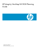
1 NonStop NS1200 System Overview The Integrity NonStop NS1200 system combines up to eight HP Integrity rx2660 servers with the NonStop operating system. Each HP Integrity rx2660 server is adapted for use as a blade element containing one single-core Intel® Itanium® processor and a ServerNet PCI adapter card to provide connectivity to the ServerNet fabrics. The Integrity NonStop NS1200 server supports configurations of two, four, six, or eight processors.
Figure 1-1 Example of an Integrity NonStop NS1200 System NonStop Architecture The Integrity NonStop NS1200 server achieves full software fault tolerance by running the NonStop operating system on rx2660 blade elements.
are duplicated to prevent any single point of failure. in the event of a processor failure, another processor takes over. The Integrity NonStop NS1200 uses the ServerNet fabric and the same modular I/O as other Integrity NonStop NS-series servers. NonStop NS1200 Hardware A large number of enclosure combinations is possible within the modular cabinets of an Integrity NonStop NS1200 server.
Each VIO enclosure contains: • • • • • Connectivity for up to eight processors, configured in pairs Four embedded Fibre Channel ports and four optional ESS (Fibre Channel) ports for communicating with storage devices such as a “Fibre Channel Disk Module” (page 18), magnetic tape devices, or an Enterprise Storage System (ESS) disk Up to eight copper/optical Ethernet ports used for Ethernet connectivity Two fans to provide the cooling for components inside a VIO enclosure Two power supplies with universal A
The Integrity NonStop NS1200 system requires multiple connections to the maintenance switch: • • • • One connection from the ME ENET port on each of the two VIO enclosures One connection from slot 6B, port A on each of the two VIO enclosure for the OSM Service Connection and OSM Notification Director: One connection to the optional UPS module One connection for the system console running OSM System Console A system console is a Windows Server purchased from HP that runs maintenance and diagnostic software
For power and environmental requirements, planning, installation, and emergency power-off (EPO) instructions for the R5500 XR UPS, refer to the documentation shipped with the UPS. Enterprise Storage System (Optional) An Enterprise Storage System (ESS) is a collection of magnetic disks, their controllers, and a disk cache in one or more standalone cabinets.
For fault tolerance, the primary and backup paths to an ESS logical device (LDEV) must go through different Fibre Channel switches. Some storage area procedures, such as reconfiguration, can cause the affected switches to pause. If the pause is long enough, I/O failure occurs on all paths connected to that switch. If both the primary and the backup paths are connected to the same switch, the LDEV goes down. Refer to the documentation that accompanies the ESS.
Term Definition Slot (or Bay or Position) A subset of a module that is the logical or physical location of a component within that module. Port A connector to which a cable can be attached and which transmits and receives data. Group-Module-Slot (GMS) A notation method used by hardware and software in NonStop systems for organizing and identifying the location of certain hardware components.
Blade Element Group-Module-Slot Numbering • Group: — In OSM Service Connection displays, 400 through 407 relates to blade complexes 0 through 7. Each blade complex includes a blade element and its associated processor. Example: group 403 = blade complex 3 — In the OSM Low-Level Link, 400 relates to all blade complexes.
NOTE: In OSM, if a blade element is not present or is powered off, processors might be renumbered. For example, if processor 3 has been removed, processor 4 becomes processor 3 in OSM displays. GMS Numbering Displayed in the OSM Service Connection: Processor ID Group* Module Slot Blade Element Processor 0 400 1 100 1 401 1 101 2 402 1 102 3 403 1 103 4 404 1 104 5 405 1 105 6 406 1 106 7 407 1 107 1, PCI adapter card.
This illustration shows the physical GMS numbering for the rear view of a blade element: Component Location and Identification 25
VIO Enclosure Group-Module-Slot Numbering An Integrity NonStop NS1200 system supports a single pair of VIO enclosures, identified as group 100: VIO Enclosure Group 100 Item Module Slot X Fabric Y Fabric Displayed by OSM Displayed on Chassis 2 3 1 1 Fibre Channel 1 - 4 ports 2 2 Processor ports (processors 4-7) 3 3 Not supported 4 3 Not supported 5 5 Not supported 6 6a Ethernet ports C and D (optical) (10/100/1000 Mbps) 6 6b Ethernet ports A, B (10/100 (copper) Mbps)C, D (10/100
Component Location and Identification 27
Fibre Channel Disk Module Group-Module-Slot Numbering This table shows the default numbering for the Fibre Channel disk module: VIO Enclosure FCDM Group Module Slot Port Shelf Slot Item 100 2 - X fabric; 1 or 7c 1, 2 1 - 4 if daisy chained); 0 FCDM 1-14 Disk drives bays 89 Transceiver A1 90 Transceiver A2 91 Transceiver B1 92 Transceiver B2 93 Left FC_AL board 94 Right FC_AL board 95 Left power supply 96 Right power supply 97 Right blower 98 Left blower 99 EMU 3 - Y f
System Installation Document Packet To keep track of the hardware configuration, internal and external communications cabling, IP addresses, and connect networks, assemble and retain as the systems records an Installation Document Packet.
2 Site Preparation Guidelines This section describes power, environmental, and space considerations for your site. Modular Cabinet Power and I/O Cable Entry Power and I/O cables can enter the Integrity NonStop NS1200 server from either the top or the bottom rear of the modular cabinets, depending on how the cabinets are ordered from HP and the routing of the AC power feeds at the site.
Power Quality This equipment is designed to operate reliably over a wide range of voltages and frequencies, described in “Enclosure AC Input” (page 43). However, damage can occur if these ranges are exceeded. Severe electrical disturbances can exceed the design specifications of the equipment.
NOTE: Retrofitting a system in the field with a UPS and ERMs will likely require moving all installed enclosures in the rack to provide space for the new hardware. One or more of the enclosures that formerly resided in the rack might be displaced and therefore have to be installed in another rack that would also need a UPS and ERMs installed. Additionally, lifting equipment might be required to lift heavy enclosures to their new location.
the hardware installed in each cabinet. For air temperature levels at the site, refer to “Operating Temperature, Humidity, and Altitude” (page 48). Weight Because modular cabinets for Integrity NonStop NS1200 servers house a unique combination of enclosures, total weight must be calculated based on what is in the specific cabinet, as described in “Modular Cabinet and Enclosure Weights With Worksheet ” (page 47).
pallets using supplied ramps. Also be sure adequate personnel are present to remove each cabinet from its shipping pallet and to safely move it to the installation site. WARNING! A fully populated cabinet is unstable when moving down the unloading ramp from its shipping pallet. Arrange for enough personnel to stabilize each cabinet during removal from the pallet and to prevent the cabinet from falling. A falling cabinet can cause serious or fatal personal injury.
3 System Installation Specifications This section provides specifications necessary for system installation planning. NOTE: All specifications provided in this section assume that each enclosure in the modular cabinet is fully populated. The maximum current for each AC service depends on the number and type of enclosures installed in the modular cabinet. Power, weight, and heat loads are less when enclosures are not fully populated; for example, a Fibre Channel disk module with fewer disks.
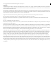
Figure 3-1 Bottom AC Power Feed Figure 3-2 shows the power feed cables on PDUs with AC feed at the top of the cabinet: Figure 3-2 Top AC Power Feed If your system includes the optional rackmounted HP R5500 XR UPS, the modular cabinet will have one PDU located on the rear left side and four extension bars on the rear right side. The PDU and extension bars are oriented inward, facing the components within the rack. To provide redundancy, components are plugged into the left-side PDU and the extension bars.
Figure 3-3 (page 39) shows the power feed cables for the PDU and optional UPS when AC power is fed from the top of the cabinet.
Figure 3-4 Bottom AC Power Feed With UPS and ERM Installed Each PDU is wired to distribute the load segments to its receptacles. CAUTION: If you are installing Integrity NonStop NS1200 system enclosures in a rack, balance the current load among the available load segments. Using only one of the available load segments, especially for larger systems, can cause unbalanced loading and might violate applicable electrical codes.
Power can enter the Integrity NonStop NS1200 server from either the top or the bottom rear of the modular cabinets, depending on how the cabinets are ordered from HP and the AC power feeds are routed at the site. Integrity NonStop NS1200 server cabinets can be ordered with the AC power cords for the PDU installed either: • • Top: Power and I/O cables are routed from above the modular cabinet.
International: 380 to 415 V AC PDU Power The cabinet includes two power distribution units (PDU). The PDU power characteristics are: PDU input characteristics • • • • 380 to 415 V ac, 3-phase Wye, 16A RMS, 5-wire 50/60Hz IEC309 5-pin, 16A input plug 6.
These ratings apply to systems with the optional rackmounted HP Model R5500 XR Integrated UPS: Version Operating Voltage Settings North America and Japan 200/208,1 220, 230, 240 5000/4500 L6-30P Dedicated 30 Amp Other International 200, 230,1 240 6000/5400 IEC-309 32 Amp Dedicated 30 Amp If 200/208 Then 5000/4500 1 Power Out (VA/Watts) Input Plug Branch Circuit (see preceding “CAUTION”) Factory-default setting For complete information and specifications, refer to the HP UPS R5500 XR Models
NOTE: If your system includes the optional rackmounted HP R5500 XR UPS, the modular cabinet will have one PDU located on the rear left side and four extension bars on the rear right side. To provide redundancy, components are plugged into the left-side PDU and the extension bars. Each extension bar is plugged into the UPS.
Plan View of the 36U and 42 U Modular Cabinets Service Clearances for the Modular Cabinets Aisles: 6 feet (182.9 centimeters) Front: 3 feet (91.4 centimeters) Rear: 3 feet (91.
36U Modular Cabinet Physical Specifications Item Height Width Depth Weight in. cm in. cm in. cm Modular cabinet 68.6 174.3 24.0 60.96 46.7 118.6 Rack 68.4 173.8 23.62 60.0 42.5 108.0 Front door 68.4 173.8 23.5 59.7 3.2 8.1 Left-rear door 68.4 173.8 11.0 27.9 1.0 2.5 Right-rear door 68.4 173.8 12.0 30.5 1.0 2.5 Shipping (palletized) 75.25 191.2 35.75 90.80 54.25 137.80 Depends on the enclosures installed.
EnclosureType Height Width Depth in cm in cm in cm 1.73 4.39 17.4 44.2 9.3 23.62 Rackmount 1.7 system console with keyboard and display 4.3 16.8 42.7 24.0 60.9 R5500 XR UPS 5.1 13.0 17.5 44.5 26.0 66.0 Extended 5.1 runtime module (ERM) 13.0 17.5 44.5 25.1 63.8 Maintenance switch (Ethernet) Modular Cabinet and Enclosure Weights With Worksheet The total weight of each modular cabinet is the sum the weights of the cabinet plus each enclosure installed in it.
NOTE: Cabinet stability is of special concern when equipment is routinely installed, removed, or accessed within the cabinet. Stability is addressed through the use of leveling feet, baying kits, fixed stabilizers, and/or ballast.
Specification Operating Range1 Humidity 15% to 80%, noncondensing 40% to 50%, noncondensing 6%, noncondensing Altitude2 0 to 10,000 feet (0 to 3,048 meters) 1 2 Recommended Range1 - Maximum Rate of Change per Hour - Operating and recommended ranges refer to the ambient air temperature and humidity measured 19.7 in. (50 cm) from the front of the air intake cooling vents. For each 1000 feet (305 m) increase in altitude above 10,000 feet (up to a maximum of 15,000 feet), subtract 1.5× F (0.
• Two rackmounted system consoles • Two rackmounted keyboard/monitor units • Two maintenance switches • One 42U high cabinet For a total thermal load for a system with multiple cabinets, add the heat outputs for all the cabinets in the system.
4 System Configuration Guidelines This section provides configuration guidelines for an Integrity NonStop NS1200 system. Integrity NonStop NS1200 systems use a flexible modular architecture. Therefore, various configurations of the system’s modular components are possible within configuration restrictions stated in this section and Chapter 5 (page 63).
Processor ID Assignment for the Blade Element Each blade element contains one processor element. The maintenance entity (ME) firmware running in the VIO enclosure assigns a number to each processor element based on its connection from the blade element to the ServerNet-to-processor ports in slots 14.1 through 14.4 (processors 0 through 3) and slots 2.1 through 2.4 (processors 4 through 7).
This illustration shows the locations of the hardware in the Fibre Channel disk module as well as the Fibre Channel port connectors at the back of the enclosure: Fibre Channel disk modules connect to Fibre Channel ports on the VIO enclosure via Fiber Channel arbitrated loop (FC-AL) cables. For more information, see “Fibre Channel Disk Module” (page 18).
Fibre Channel port location and cable connections vary depending on the various controller and Fibre Channel disk module combinations. Configurations for Fibre Channel Devices Each VIO enclosure in an Integrity NonStop NS1200 system contains four Fibre Channel ports that support up to 16 Fibre Channel disk modules (FCDMs) in a daisy-chained configuration, with identification of the FCDMs depending on the ServerNet connection to the Fibre Channel ports on the VIO enclosure.
• • • • • • • • • • Ethernet ports are located in slots 6b, 6a/7a, and 7b of a VIO enclosure. The group number for a VIO enclosure is 100. With primary and mirror FCDMs in the same cabinet, the primary FCDM resides in a lower U than the mirror FCDM. Fibre Channel disk drives are configured with dual paths. Where possible, Fibre Channel ports and FCDMs are configured with four Fibre Channel ports and four FCDMs for maximum fault tolerance.
This table lists the Fibre Channel port group-module-slot-port (GMSP) and disk group-module-shelf-bay (GMSB) identification for the factory-default system disk locations in the configuration of four Fibre Channel ports, two FCDMs, and two VIO enclosures: Disk Volume Name Fibre Channel Port GMSP Disk GMSB1 $SYSTEM (primary) 100.2.1.1 and 100.3.1.1 100.211.101 $DSMSCM (primary) 100.2.1.1 and 100.3.1.1 100.211.102 $AUDIT (primary) 100.2.1.1 and 100.3.1.1 100.211.103 $OSS (primary) 100.2.1.
This table lists the Fibre Channel port group-module-slot-port (GMSP) and disk group-module-shelf-bay (GMSB) identification for the factory-default system disk locations in the configuration of eight Fibre Channel ports, four FCDMs, and two VIO enclosures: Disk Volume Name Fibre Channel Port GMSP Disk GMSB1 $SYSTEM (primary 1) 100.2.1.1 and 100.3.1.1 100.211.101 $DSMSCM (primary 1) 100.2.1.1 and 100.3.1.1 100.211.102 $AUDIT (primary 1) 100.2.1.1 and 100.3.1.1 100.211.103 $OSS (primary 1) 100.2.
Disk Volume Name Fibre Channel Port GMSP Disk GMSB1 $DSMSCM (mirror 2) 100.2.1.4 and 100.3.1.4 100.214.102 $AUDIT (mirror 2) 100.2.1.4 and 100.3.1.4 100.214.103 $OSS (mirror 2) 100.2.1.4 and 100.3.1.4 100.214.104 1 For an illustration of the factory-default slot locations for an FCDM, see “Factory-Default Locations for Disk Volumes” (page 53).
Two VIO enclosures, two Fibre Channel ports, and four FCDMs with an ID expander do not provide fault-tolerant mirrored disk storage. Installing each mirrored disk in the same corresponding FCDM and bay number as its primary disk is not required, but it is recommend to simplify the physical management and identification of the disks.
For an illustration of a conceptual example for network connectivity to a LAN, see “Primary and Backup System Consoles Managing One System” (page 75). Default Naming Conventions The Integrity NonStop NS1200 system implements default naming conventions in the same manner as other Integrity NonStop NS-series systems. With a few exceptions, default naming conventions are not necessary for the modular resources that make up an Integrity NonStop NS1200 system.
NOTE: Naming conventions or configurations for the dedicated service LAN TCP/IP are the same as the TCP/IP conventions used with G-series RVUs. The names are $ZTCP0 and $ZTCP1. CAUTION: Do not change the process names for $ZTCP0 and $ZTCP1. Doing so will make some components inaccessible. OSM Service Connection provides the location of the resource by adding an identifying suffix to the names of all the system resources. Other interfaces, such as SCF, also provide means to locate named resources.
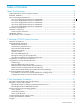
5 Hardware Configuration in Modular Cabinets This section shows locations of hardware components within 36 and 42 U modular cabinets for an Integrity NonStop NS1200 server. A number of physical configurations are possible because of the flexibility inherent to the NonStop architecture and ServerNet network. NOTE: Hardware configuration drawings in this section represent the physical arrangement of the modular enclosures but do not show PDUs.
Enclosure or Component Height (U) Required Cabinet (Rack) Location Notes Cabinet stabilizer N/A Bottom front exterior of cabinet Required when you have less than four cabinets bayed together. Cabinet stabilizer is not required when cabinet is bolted to its adjacent cabinet. Blade element 2U Any available 2U space. Lower U locations are recommended. If the optional UPS and ERM are installed in 36U cabinets, two cabinets are needed to accommodate eight blade elements.
Figure 5-1 36U and 46U Configurations These options can be installed in locations marked Configurable Space in the configuration drawings: • • • Maintenance switch: 1U required, preferably at the top or bottom of the cabinet. Console: 2U required, with recommended installation at cabinet offset 20U Fibre Channel disk module: 3U required A second cabinet is required when: • Eight blade elements are needed in a server that has a 36U cabinet with the optional UPS and ERM.
Example Cabling for a 2-Processor System This illustration shows an example of a 2-processor system. This simplified, conceptual representation shows the X and Y ServerNet cabling between the blade elements, VIO enclosures, and Fibre Channel disk modules. The example of Fibre Channel disk module configuration for the group 100 VIO enclosures is described in more detail in “Four Fibre Channel Ports, Two FCDMs, Two VIO Enclosures” (page 55). To simplify the drawing, power and Ethernet cables are not shown.
6 Maintenance and Support Connectivity Local monitoring and maintenance of the NonStop NS1200 system occurs over the dedicated service LAN. The dedicated service LAN provides connectivity between the system console and the maintenance firmware in the system hardware. Remote support is provided by OSM, which runs on the system console and communicates over the HP Instant Support Enterprise Edition infrastructure or an alternative remote access solution.
Dedicated Service LAN An Integrity NonStop NS1200 system requires a dedicated LAN for system maintenance through OSM. Only components specified by HP can be connected to a dedicated LAN. No other access to the LAN is permitted.
Fault-Tolerant Configuration • • • • Connect one system console to each maintenance switch. Connect the VIO enclosure for the X fabric to one of the maintenance switches and the VIO enclosure for the Y fabric to the other maintenance switch. Connect one Ethernet port in each VIO enclosure to each maintenance switch. Connect one maintenance switch to an HP extension bar that is powered by the UPS. HP extension bars are installed in place of a PDU on the rear right side of the modular cabinet.
Component Group.Module.Slot Default IP Address Used By Primary system console (rackmounted or stand-alone) N/A 192.231.36.1 OSM Low-Level Link OSM Service Connection OSM Notification Director Backup system console (rackmounted only) N/A 192.231.36.4 Up to two additional system N/A consoles (rackmounted only) 192.231.36.5 Blade iLO 192.231.36.40 N/A 192.231.36.6 192.231.36.41 192.231.36.42 192.231.36.43 192.231.36.
If a DHCP server is already present on the network to which these components will be connected, you can use that server. If your network is not equipped with a DHCP server, work with your account team to identify available options. Some guidelines for configuring the DHCP server: • • Configure the range of IP addresses to be assigned dynamically by the DHCP server to be in the same subnet as existing IP addresses on the LAN and any static IP address included in the dedicated service LAN.
For a fault-tolerant dedicated service LAN, two Ethernet ports are required; one port located in VIO enclosure module 2 for X ServerNet fabric connectivity, and one port located in VIO enclosure module 3 for Y ServerNet fabric connectivity. When the Ethernet port provides connection to the dedicated service LAN, use the slower 10/100 Mbps PIF A rather than one of the high-speed 1000 Mbps Ethernet ports of PIF C or D.
The values in this table show the identification for the Ethernet ports in the preceding illustration: GMS for Ethernet Port Ethernet PIF Location in VIO Enclosure Ethernet LIF TCP/IP Stack IP Configuration 100.2.6b Port A G10026.0.A L1002R $ZTCP0 IP: 192.231.36.10 GW: 192.231.36.9 Subnet: %hFFFFFF00 Hostname: osmlanx 100.3.6b Port A G10036.0.A L1003R $ZTCP1 IP: 192.231.36.11 GW: 192.231.36.
Your system console configuration can be: • • One system console managing one system (not recommended) Multiple system consoles managing one system For Information About ... Refer to ...
The one system console on the LAN must be configured as the primary system console. This configuration can be called the setup configuration and is used during initial setup and installation of the system console and the server. When you use this configuration, you do not need to change the preconfigured IP addresses. The setup configuration is an example of a secure, stand-alone network.
NOTE: A subnet is a network division within the TCP/IP model. Within a given network, each subnet is treated as a separate network. Outside that network, the subnets appear as part of a single network. The terms subnet and subnetwork are used interchangeably. If a remote maintenance LAN connection is required, use the second network interface card (NIC) in the NonStop system console to connect to the operations LAN, and access the other devices in the maintenance LAN using Remote Desktop via the console.
A Cables Internal Cables Available internal cables and their lengths are: Cable Type Connectors Length (meters) Length (feet) Product ID MMF LC-LC 2 7 M8900-02 3 9 M8900-03 5 16 M8900-05 6 19 M8900-06 10 32 M8900-10 15 49 M8900-15 40 131 M8900-40 80 262 M8900-80 100 328 M8900100 1251 4101 M8900125 200 1 656 1 M8900200 2501 8201 M8900250 10 33 M8910-10 20 66 M8910-20 50 164 M8910-50 1251 4101 M8910125 3.15 10.
Cable Length Restrictions Maximum allowable lengths of cables connecting the modular system components are: Connection Connectors Maximum Length Product ID Blade element to VIO MMF enclosure (ServerNet-to-processor port) LC-LC 125 m M8900nnn1 VIO enclosure to VIO MMF enclosure (cross-link connection) LC-LC 50m M8900nnn1 VIO enclosure (Fibre MMF Channel port) to Fibre Channel disk module LC-LC 250 m M8900nnn1 VIO enclosure (Fibre Channel port) to ESS MMF LC-LC 250 m M8900nnn1 VIO enclosu
B Operations and Management Using OSM Applications NOTE: HP Insight Remote Support Advanced (Insight RSA) is now qualified for Integrity NonStop NS-Series servers. Insight RSA is the go-forward remote support solution for NonStop systems, replacing the OSM Notification Director in both modem-based and HP Instant Support Enterprise Edition (ISEE) remote support solutions.
AC Power Monitoring Integrity NonStop NS1200 servers require either the optional HP model R5500 XR UPS (with one or two ERMs for additional battery power) or a user-supplied UPS installed in each modular cabinet, or a user-supplied site UPS to support system operation through power transients or an orderly system shutdown during a power failure. If the HP R5500 XR UPS is installed, it is connected to the system’s dedicated service LAN via the maintenance switch where OSM monitors the power state.
NOTE: For NonStop BladeSystems, these actions are located under the Enclosure object. For NonStop NS-series servers, the actions are located under the Power Supply units located in either P-switches, IOAM, or VIO modules (depending on system type). How OSM Power Failure Support Works NOTE: OSM power failure support works as described only after it has been properly configured.
A rack-mounted UPS can often supply five minutes of power with some extra capacity for contingencies, provided the batteries are new and fully charged. This five minute figure is an estimate used for illustration in this discussion, not a guarantee for any specific configuration. You must ensure that the battery capacity for a fully-powered system allows for at least two minutes after OSM initiates the orderly shutdown to allow the disk cache to be flushed to nonvolatile media.
C Default Startup Characteristics NOTE: The configurations documented here are typical for most sites. Your system load paths might be different, depending upon how your system is configured. To determine the configuration of your system, refer to the system attributes in the OSM Service Connection. You can select this from within the System Load dialog box in the OSM Low-Level Link.
This illustration shows the system load paths: The command interpreter input file (CIIN) is automatically invoked after the first processor is loaded. The CIIN file shipped with new systems contains the TACL RELOAD * command, which loads the remaining processors. For default configurations of the Fibre Channel ports, Fibre Channel disk modules, and load disks, see “Example Configurations of the VIO Enclosures and FCDMs” (page 55).
Index Symbols $SYSTEM disk locations, 83 A AC current calculations, 49 AC power 208 V ac 3-phase delta 24A RMS, 41 enclosure input specifications, 43 input, 41 power-fail monitoring, 80 power-fail states, 82 unstrapped PDU, 40 AC power feed, 37 bottom of cabinet, 37 top of cabinet, 38 with cabinet UPS, 39 air conditioning, 33 air filters, 34 B blade complex, 22 blade element defined, 22 processor ID, 17 branch circuit, 42 C cabinet, 21 cabinet dimensions, 45 cable length restrictions, 51, 78 cabling blad
group-module-slot (GMS), 22 H hardware configurations typical, 64 heat calculation, 33, 48 heat disipation,Btu/hour, enclosures, 48 height in U, enclosures, 45 hot spots, 33 I input power, 41 inrush current, 32 Integrity NonStop NS1200 server characteristics, 15 internal cable product IDs, 77 IP addresses dynamic, 70 static, 70 L LAN non-fault-tolerant maintenance, 68 service, G4SA PIF, 72 load operating system paths, 83 M maintenance architecture, 67 maintenance switch, 18 metallic particulate contamin
HP R5500 XR, 19, 32, 43 user-supplied rackmounted, 33 user-supplied site, 33 V VIO enclosure configuration considerations, 52 description, 17 disk storage considerations, 52 enclosure location in cabinet, 64 FCDM control, 52 Fibre Channel tape device connection, 52 GMS numbering, 26 maintenance switch connection, 19 W weight calculation, 34, 47 worksheet heat calculation, 48 weight calculation, 47 Z zinc, cadmium, or tin particulates, 34 87