HP Integrity NonStop NS14000 Planning Guide HP Part Number: 543635-003 Published: May 2007 Edition: H06.
© Copyright 2007 Hewlett-Packard Development Company, L.P. Legal Notice Confidential computer software. Valid license from HP required for possession, use or copying. Consistent with FAR 12.211 and 12.212, Commercial Computer Software, Computer Software Documentation, and Technical Data for Commercial Items are licensed to the U.S. Government under vendor’s standard commercial license. The information contained herein is subject to change without notice.
Table of Contents About This Document.........................................................................................................9 Supported Release Version Updates (RVUs)..........................................................................................9 Intended Audience.................................................................................................................................9 New and Changed Information in This Edition.............................................
Dimensions and Weights......................................................................................................................28 Plan View From Above the Modular Cabinet ................................................................................28 Service Clearances for the Modular Cabinet...................................................................................28 Unit Sizes...........................................................................................................
Versatile I/O (VIO) Enclosure..........................................................................................................60 Fibre Channel Disk Module (FCDM)..............................................................................................62 Tape Drive and Interface Hardware................................................................................................62 Maintenance Switch (Ethernet)....................................................................................
A Cables........................................................................................................................105 Internal Cables....................................................................................................................................123 ServerNet Cluster Cables....................................................................................................................106 Cable Length Restrictions............................................................
List of Tables 1-1 1-2 3-1 3-2 3-3 Figure 1-1. Integrity NonStop NS14000 Server.............................................................................14 Figure 1-1. Example of an Integrity NonStop NS14000 System....................................................15 Figure 3-1. Example Duplex Configuration..................................................................................33 Example Load Calculations for Cabinet One.........................................................................
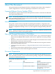
About This Document This guide describes the HP Integrity NonStop™ NS14000 system and provides examples of system configurations to assist you in planning for installation of a new system. Supported Release Version Updates (RVUs) This publication supports H06.10 and all subsequent H-series RVUs until otherwise indicated by its replacement publication. NOTE: For NonStop NS14000 servers that contain I/O Adapter Module (IOAM) enclosures, refer to the H06.
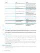
Section Title Contents 3 System Installation Specifications This section provides the installation specifications for fully populated Integrity NonStop NS14000 enclosures. 4 Integrity NonStop NS14000 System Description This section introduces the NonStop advanced architecture (NSAA) and the Integrity NonStop NS14000 system. 5 Modular System Hardware This section includes topics to consider when you are planning or upgrading the installation site.
Publishing History Part Number Product Version Publication Date 543635-001 N.A. November 2006 543635-002 N.A. January 2007 543635-003 N.A. May 2007 HP Encourages Your Comments HP encourages your comments concerning this document. We are committed to providing documentation that meets your needs. Send any errors found, suggestions for improvement, or compliments to: pubs.comments@hp.
1 System Hardware Overview Overview of the Integrity NonStop NS14000 System The Integrity NonStop NS14000 server uses Intel® Itanium® processors and NonStop advanced architecture (NSAA) in duplex and triplex configurations. It uses much of the same modular system hardware as other Integrity NonStop NS-series servers.
Table 1-1 Figure 1-1.
Table 1-2 “Figure 1-1. Example of an Integrity NonStop NS14000 System” shows the rear view of an example Integrity NonStop NS14000 system with a duplex processor in a 42U modular cabinet without the optional UPS and ERM. Table 1-2 Figure 1-1. Example of an Integrity NonStop NS14000 System Preparation for Other Server Hardware This guide provides the specifications only for the Integrity NonStop NS14000 server modular cabinet and enclosures identified earlier in this section.
2 Installation Facility Guidelines Modular Cabinet Power and I/O Cable Entry Power and I/O cables can enter the Integrity NonStop NS14000 server from either the top or the bottom rear of the modular cabinets, depending on how the cabinets are ordered from HP and the routing of the AC power feeds at the site. Integrity NonStop NS14000 server cabinets can be ordered with the AC power cords for the PDUs exiting either: • • Top: Power and I/O cables are routed from above the modular cabinet.
Power Quality This equipment is designed to operate reliably over a wide range of voltages and frequencies, described in Enclosure AC Input on page 3-5. However, damage can occur if these ranges are exceeded. Severe electrical disturbances can exceed the design specifications of the equipment.
For power information, refer to “Model R5500 XR Integrated UPS” (page 27). For complete information and specifications on the R5500 XR UPS, contact your HP representation or refer to the HP UPS R5500 XR Models User Guide available at: http://h10032.www1.hp.com/ctg/Manual/c00065453.
Weight Because modular cabinets for Integrity NonStop NS14000 servers house a unique combination of enclosures, total weight must be calculated based on what is in the specific cabinet, as described in Modular Cabinet and Enclosure Weights With Worksheet on page 3-10. Flooring Integrity NonStop NS14000 servers can be installed either on the site’s floor with the cables entering from above the equipment or on raised flooring with power and I/O cables entering from underneath.
but also all required personnel and lifting or moving devices. If necessary, enlarge or remove any obstructing doorway or wall. All modular cabinets have small casters to facilitate moving them on hard flooring from the unpacking area to the site. Because of these small casters, rolling modular cabinets along carpeted or tiled pathways might be difficult. If necessary, plan for a temporary hard floor covering in affected pathways for easier movement of the equipment.
3 System Installation Specifications All specifications provided in this section assume that each enclosure in the modular cabinet is fully populated; for example, a NonStop Blade Element with four processors and maximum memory. The maximum current for each AC service depends on the number and type of enclosures installed in the modular cabinet.
NOTE: If your system includes the optional rackmounted HP R5500 XR UPS, the modular cabinet will have one PDU located on the rear left side and four extension bars on the rear right side. To provide redundancy, components are plugged into the left-side PDU and the extension bars. Each extension bar is plugged into the UPS. The R5500 XR UPS AC input power cord is routed as described above, and the large output receptacle is unused.
International: 380 to 415 V AC PDU Power The PDU power characteristics are: PDU input characteristics • • • • 380 to 415 V ac, 3-phase Wye, 16A RMS, 5-wire 50/60Hz IEC309 5-pin, 16A input plug 6.
CAUTION: Be sure the hardware configuration and resultant power loads of each cabinet within the system do not exceed the capacity of the branch circuit according to applicable electrical codes and regulations. NOTE: If your system includes the optional rackmounted HP R5500 XR UPS, the modular cabinet will have one PDU located on the rear left side and four extension bars on the rear right side. To provide redundancy, components are plugged into the left-side PDU and the extension bars.
NOTE: If your system includes the optional rackmounted HP R5500 XR UPS, the modular cabinet will have one PDU located on the rear left side and four extension bars on the rear right side. To provide redundancy, components are plugged into the left-side PDU and the extension bars. Each extension bar is plugged into the UPS.
Dimensions and Weights This subsection provides information about the dimensions and weights for modular cabinets and enclosures installed in a modular cabinet and covers these topics: • • • • • “Service Clearances for the Modular Cabinet” (page 28) “Unit Sizes” (page 28) “Modular Cabinet Physical Specifications” (page 29) “Enclosure Dimensions” (page 29) “Modular Cabinet and Enclosure Weights With Worksheet ” (page 30) Plan View From Above the Modular Cabinet Service Clearances for the Modular Cabinet A
Enclosure Type Height (U) Extended runtime module 3 Rackmount console 2 Modular Cabinet Physical Specifications Item Height Width Depth Weight in. cm in. cm in. cm Modular cabinet 78.7 199.9 24.0 60.96 46.0 116.84 Rack 78.5 199.4 23.62 60.0 40.0 101.9 Front door 78.5 199.4 23.5 59.7 3.0 7.6 Left-rear door 78.5 199.4 11.0 27.9 1.0 2.5 Right-rear door 78.5 199.4 12.0 30.5 1.0 2.5 Shipping (palletized) 86.22 219.0 32.0 81.28 54.0 137.
Modular Cabinet and Enclosure Weights With Worksheet The total weight of each modular cabinet is the sum the weights of the cabinet plus each enclosure installed in it. Use this worksheet to determine the total weight: Enclosure Type Number of Enclosures Weight Total lbs kg 42U modular cabinet* 303 137.44 NonStop Blade Element 112 50.8 Processor switch 70 32.8 LSU 96 43.5 VIO enclosure 68 30.84 Fibre Channel disk module 78 35.4 Maintenance switch (Ethernet) 6 2.
Heat Dissipation Specifications and Worksheet EnclosureType Unit Heat (Btu/hour with single AC line powered) Unit Heat (Btu/hour with both AC lines powered) 2320 2423 2594 2662 LSU (with four LSUs) 512 750 VIO enclosure1 893 1112 Fibre Channel disk module2 990 1187 Maintenance switch (Ethernet)3 150 - Rackmount console system unit with keyboard and display 696 - 4-processor NonStop Blade Element: Number Installed Total (BTU/hour) 16 GB memory boards 32 GB memory boards 1 Measured wit
Cooling Airflow Direction Each enclosure includes its own forced-air cooling fans or blowers. Air flow for each enclosure enters from the front of the modular cabinet and exhausts at the rear. Typical Acoustic Noise Emissions 70 dB(A) (sound pressure level at operator position) Tested Electrostatic Immunity • • Contact discharge: 8 KV Air discharge: 20 KV Calculating Specifications for Enclosure Combinations “Figure 3-1.
Table 3-1 Figure 3-1. Example Duplex Configuration Table 3-2 Example Load Calculations for Cabinet One Component Quantity Height (U) Weight (lbs) Weight (kg) Volt-amps, one feed powered Volt-amps, both feeds powered Heat (Btu) NonStop Blade Element 2 10 224 152.4 1420 1560 5324 LSU 1 4 96 43.5 150 220 750 VIO enclosure 2 8 136 61.68 524 652 2224 Fibre 2 Channel disk module 6 156 70.
Table 3-2 Example Load Calculations for Cabinet One (continued) Component Quantity Height (U) Weight (lbs) Weight (kg) Volt-amps, one feed powered Volt-amps, both feeds powered Heat (Btu) Console - - - - - - - Maintenance 1 switch 1 6 2.7 44 - 150 Cabinet 1 42 303 137.4 - - - Total - 42 921 468.
4 Integrity NonStop NS14000 System Description NonStop Advanced Architecture Integrity NonStop NS14000 systems employ a unique method for achieving fault tolerance in a clustered processor environment: the modular NonStop advanced architecture (NSAA). NSAA utilizes standard Intel Itanium microprocessors, without cycle-by-cycle lock-stepping. Instead, two or three microprocessors run the same instruction stream concurrently in a loose lockstep process.
In the event of a processor fault in either a duplex or triplex processor, the failed component within a NonStop Blade Element (processor element, power supply, and so forth) or the entire Blade Element can be replaced while the system continues to run. A single Integrity NonStop NS14000 system can have up to two NonStop Blade Complexes for a total of eight processors. Processors communicate with each other and with the system I/O over dual ServerNet fabrics.
In summary, these terms describe the NSAA processor: Term Description Processor element (PE) A single Itanium microprocessor with its associated memory. A PE is capable of executing an individual instruction stream and I/O communication through fiber-optic links. NonStop Blade Element Two or four PEs contained within a single NonStop Blade Element enclosure. Logical processor One or more PEs from each NonStop Blade Element executing a single instruction stream.
Triplex Processor The TMR or triplex processor uses three NonStop Blade Elements, A, B, and C. As with the duplex processor, the fiber-optic cables connect the PEs to the LSUs, and these LSUs then connect to the two independent ServerNet fabrics via the VIO enclosure. Dual ServerNet fabrics create communications redundancy in case one of the fabrics fails. For a description of the LSU functions, see “Processor Synchronization and Rendezvous” (page 39).
In a TMR or triplex processor, each LSU has inputs from three PEs. As with the duplex processor, the LSU keeps the three PEs in loose lockstep. The triplex processor provides fault tolerance upon failure of a PE by comparing the output from the three NonStop Blade Elements to determine which one is errant. This method eliminates the question of which output is valid when two outputs disagree in a duplex system.
Memory Reintegration Memory reintegration initiates processing in a PE whose operation has been stopped because the NonStop Blade Element diverged or has been replaced. This reintegration requires that all of the memory and processor states be copied from a functioning PE to the target PE. Once the memory and processor state data is copied, rendezvous is used to complete the reintegration. This entire reintegration operation is invisible to the running applications.
NOTE: For NonStop NS14000 servers that contain I/O Adapter Module (IOAM) enclosures, refer to the H06.07 (or earlier) version of this manual for planning, configuration, and maintenance information of the IOAM enclosure. Overview of the ServerNet Fabric ServerNet 3 routers are used within the Integrity NonStop NS14000 systems as building blocks for the ServerNet fabric.
ServerNet Pathways in the VIO Enclosure This drawing shows the VIO enclosures ServerNet communication pathways. Optic lines connect the LSU with the ServerNet-to-processor ports in each VIO enclosure. The ServerNet-to-processor ports in VIO enclosure module 2 communicate with the X logic board. The ServerNet-to-processor ports in VIO enclosure module 3 communicate with the Y logic board.
Example of ServerNet Pathways This example shows the redundant routing and connection of the ServerNet X and Y fabric within a simple system. This example includes: • • Four processors (0 through 3) with their requisite four LSU optics adapters. Two VIO enclosures, group 100, connected to the LSUs in a NonStop Blade Complex. For configurations of the VIO enclosures and Fibre Channel disk drives, see Chapter 6 (page 75).
If a cable, connection, router, or other failure occurs, only the system resources that are downstream of the failure on the same fabric are affected. Because of the redundant ServerNet architecture, communication takes the alternate path on the other fabric to the peer resources. For example, if the logic board for the Y fabric fails, the downstream adapters and the storage or communications that connect to the failed switch board are unavailable to the system through the Y fabric.
Modular Hardware Hardware for Integrity NonStop NS14000 systems is implemented in modules (enclosures installed in modular cabinets). For descriptions of the modular hardware components, see Chapter 5 (page 49). All Integrity NonStop NS14000 server components are field-replaceable units (FRUs) that can only be serviced by service providers trained by HP. For information about installing the Integrity NonStop NS14000 server hardware, refer to the NonStop NS14000 Hardware Installation Manual.
• • 4-GB or 8-GB main memory per logical processor 16 or 32 DDR SDRAM DIMM slots Default Startup Characteristics Each Integrity NonStop NS14000 system ships with these default startup characteristics: • $SYSTEM disks residing in a Fibre Channel disk module connected to VIO enclosure group 100 with the disks in these locations: Path • • VIO Enclosure Fibre Channel Port FCDM Group Module Slot SAC Shelf Bay Primary 100 2 1 1 1 1 Backup 100 3 1 1 1 1 Mirror 100 3 1 2 1 1 Backu
The command interpreter input file (CIIN) is automatically invoked after the first processor is loaded. The CIIN file shipped with new systems contains the TACL RELOAD * command, which loads the remaining processors. For default configurations of the Fibre Channel ports, Fibre Channel disk modules, and load disks, see “Example Configurations of the VIO Enclosures and Fibre Channel Disk Modules” (page 88). For system load procedures, see the NonStop NS14000 Hardware Installation Manual.
• • Cabinet U location of the bottom edge of each enclosure Each ServerNet cable with: — Source and destination enclosure, component, and connector — Cable part number — Source and destination connection labels Configuration Forms for the ServerNet Adapters Fibre Channel ports and Ethernet ports on a VIO enclosure provide the functionality of Fibre Channel ServerNet adapters (FCSAs) and Gigabit Ethernet 4-port ServerNet adapters (G4SAs) in an Integrity NonStop NS1000 system.
5 Modular System Hardware Modular Hardware Components These hardware components can be part of an Integrity NonStop NS14000 system: • • • • • • • • • • “Modular Cabinets” (page 50) “NonStop Blade Element” (page 55) “Logical Synchronization Unit (LSU)” (page 58) “Versatile I/O (VIO) Enclosure” (page 60) “Fibre Channel Disk Module (FCDM)” (page 62) “Tape Drive and Interface Hardware” (page 62) “Maintenance Switch (Ethernet)” (page 62) “UPS and ERM (Optional)” (page 63) “Configuration Form for a ServerNet Clu
Modular Cabinets The modular cabinet is a EIA standard 19-inch, 42U, rack for mounting modular components. The modular cabinet comes equipped with front and rear doors and includes a rear extension that makes it deeper than some industry-standard racks. The Power Distribution Units (PDUs) are mounted along the rear extension without occupying any U-space in the cabinet and are oriented inward, facing the components within the modular cabinet.
NOTE: If your system includes the optional rackmounted HP R5500 XR UPS, the modular cabinet will have one PDU located on the rear left side and four extension bars on the rear right side. To provide redundancy, components are plugged into the left-side PDU and the extension bars. Each extension bar is plugged into the UPS.
— — IEC309 5-pin, 16A input plug 6.
Each PDU distributes the site AC power as single phase 200 to 240 V ac to the 39 outlets for connecting the power cords from the components mounted in the modular cabinet. These outlets provide the 180-264 V ac required by the modular hardware. The AC power feed cables for the PDUs are mounted to exit the modular cabinet at either the top or bottom rear corners of the cabinet depending on what is ordered for the site power feed.
If your system includes the optional rackmounted HP R5500 XR UPS, the modular cabinet will have one PDU located on the rear left side and four extension bars on the rear right side. The PDU and extension bars are oriented inward, facing the components within the modular cabinet. To provide redundancy, components are plugged into the left-side PDU and the extension bars. Each extension bar is plugged into the UPS.
Each PDU is wired to distribute the load segments to its receptacles. CAUTION: If you are installing Integrity NonStop NS14000 system enclosures in a modular cabinet, balance the current load among the available load segments. Using only one of the available load segments, especially for larger systems, can cause unbalanced loading and might violate applicable electrical codes.
• • • • • • • DIMMs Reintegration board for managing internal memory traffic (accessed from top of enclosure when enclosure is pulled forward on its rails) Blade optics adapter plug-in cards (PICs) with two ports; two adapters minimum, eight maximum (accessed from top of enclosure when enclosure is pulled forward on its rails) Redundant cooling fans (accessed from top of enclosure when enclosure is pulled forward on its rails) Redundant 220-240 V ac power supplies and power cords (accessed from back of of
Because the modular hardware provides considerable flexibility in how the hardware is distributed among multiple cabinets, a single cabinet could contain four NonStop Blade Elements, with each NonStop Blade Element a member of a different NonStop Blade Complex. To reduce ambiguity in identifying proper cable connections to the NonStop Blade Complex, the identification convention uses combinations of a letter to refer to each connection.
Front Panel Buttons Button Function Condition Operation Power Hard reset Power is on. Cycle power and reset or reconfigure logic. Power is in standby. Remain in standby. Power is on. Send initialize interrupt to processors, but without reset or reconfiguration of logic. TOC/NMI Soft reset Front Panel Indicator LEDs LED Indicator State Meaning Power Flashing green Power is on; NonStop Blade Element is available for normal operation. Flashing yellow NonStop Blade Element is in power mode.
The LSU module consists of two types of FRUs: • • • LSU logic board (accessible from the front of the LSU enclosure) LSU optics adapters (accessible from the rear of the LSU enclosure) AC power assembly (accessible from the rear of the LSU enclosure) CAUTION: To maintain proper cooling air flow, blank panels must be installed in all slots that do not contain logic adapter PICs or logic boards.
LSU Indicator LEDs LED State LSU optics adapter PIC (green LED) Green Off LSU optics adapter PIC (amber LED) Amber Off LSU optics adapter connectors (green Green LEDs) Meaning Power is on; LSU is available for normal operation. Power is off. Power is in progress, board is being reset, or a fault exists. Normal operation or powered off. NonStop Blade Element optics link or ServerNet link is functional. Off Power is off, or a fault exists (amber LED is on).
Because each VIO enclosure is a single module, two VIO enclosures are required to provide fault-tolerant paths. The paths must be configured through both VIO enclosures. For example, you could configure these paths through the Fibre Channel ports located on the two VIO enclosures: Path Group Module Slot.Port Primary 100 02 1.1 Primary backup 100 03 1.1 Mirror 100 03 1.2 Mirror backup 100 02 1.
These paths all exist within the same group. But they are divided between two VIO enclosures, so the configuration is fault-tolerant. For additional information, see “Fibre Channel Devices” (page 85).
The Integrity NonStop NS14000 system requires multiple connections to the maintenance switch: • • • • One connection from the ME ENET port on each of the two VIO enclosures One connection from slot 6B, port A on each of the two VIO enclosure for the OSM Service Connection and OSM Notification Director: One connection to each of the optional UPS modules One connection for each system console running OSM UPS and ERM (Optional) An uninterruptible power supply (UPS) is optional but recommended where a site UP
NOTE: The AC input power cord for the R5500 XR UPS is routed to exit the modular cabinet at either the top or bottom rear corners of the cabinet, depending on what is ordered for the site power feed, and the large output receptacle is unused. For power and environmental requirements, planning, installation, and emergency power-off (EPO) instructions for the R5500 XR UPS, refer to the documentation shipped with the UPS.
Cables and switches vary, depending on whether the connection is direct, switched, or a combination: Connection LC-LC Cables Fibre Channel Switches Direct connect 2 Fibre Channel ports 0 Switched 4 Fibre Channel ports 1 or more Combination of direct and switched 2 Fibre Channel ports for each direct 1 connection4 Fibre Channel ports for each switched connection This illustration shows an example of connections between two VIO enclosures and an ESS via separate Fibre Channel switches: For fault to
Terminology These are terms used in locating and describing components: Term Definition Cabinet Computer system housing that includes a structure of external panels, front and rear doors, internal racking, and dual PDUs. Rack Structure integrated into the cabinet into which rackmountable components are assembled. Rack Offset The physical location of components installed in a modular cabinet, measured in U values numbered 1 to 42, with 1U at the bottom of the cabinet. A U is 1.
Power Supply (100.2.15) Rack and Offset Physical Location Rack name and rack offset identify the physical location of components in an Integrity NonStop NS14000 system. The rack name is located on an external label affixed to the rack, which includes the system name plus a 2-digit rack number. Rack offset is labeled on the rails in each side of the rack. These rails are measured vertically in units called U, with one U measuring 1.75 inches (44 millimeters).
A number of GMS configurations are possible in the modular Integrity NonStop NS14000 system. This table shows the default numbering for the logical processors: Logical Processors Group (NonStop Blade Complex) Module (NonStop Blade Element) 0-3* 4-7 400 401 1 (A) 2 (B) 3 (C) Slot (Optics) Port Blade optics adapters 1-8 (software identified as slots 71-78) J0-J7, K0-K7 * Logical processor 0 must be in NonStop Blade Complex 0 (group 400). All other processors can be in any user-defined group.
Component Location and Identification 69
VIO Enclosure Group-Module-Slot Numbering An Integrity NonStop NS14000 system supports a single pair of VIO enclosures, identified as group 100: VIO Enclosure Group 100 Item Module Slot X Fabric Y Fabric Displayed by OSM Displayed on Chassis 2 3 1 1 Fibre Channel 1 - 4 ports 2 2 Processor ports (processors 4-7) 3 3 Not supported 4 3 Not supported 5 5 ServerNet cluster ports 6 6a Ethernet ports C and D (optical) (10/100/1000 Mbps) 6 6b Ethernet ports A, B (10/100 (copper) Mbps)C
Component Location and Identification 71
Fibre Channel Disk Module Group-Module-Slot Numbering This table shows the default numbering for the Fibre Channel disk module: VIO Enclosure FCDM Group Module Slot Port Shelf Slot 100 2 - X fabric; 3 - Y fabric 1 or 7c 1, 2 1 - 4 if daisy 0 chained); 1 if single disk 1-14 module Item FCDM Disk drives bays 89 Transceiver A1 90 Transceiver A2 91 Transceiver B1 92 Transceiver B2 93 Left FC_AL board 94 Right FC_AL board 95 Left power supply 96 Right power supply 97 Right blower
Component Location and Identification 73
6 System Configuration Guidelines Integrity NonStop NS14000 systems use a flexible modular architecture. Therefore, almost any configuration of the system’s modular components is possible within a few configuration restrictions stated in “Enclosure Locations in Cabinets” (page 76) and “VIO Enclosure and Disk Storage Considerations” (page 84). NOTE: For NonStop NS14000 servers that contain I/O Adapter Module (IOAM) enclosures, refer to the H06.
For other example configurations, see Chapter 7 (page 99). Enclosure Locations in Cabinets In this table, the enclosure location refers to the U in the cabinet where the lower edge of the enclosure resides, such as the bottom of a NonStop Blade Element enclosure at 28U.
Internal ServerNet Interconnect Cabling This subsection includes: • • • • • • • • • • • “Cable Labeling” (page 77) “Cable Management System” (page 78) “Internal Interconnect Cables” (page 78) “Dedicated Service LAN Cables” (page 79) “Cable Length Restrictions” (page 79) “Internal Cable Product IDs” (page 80) “NonStop Blade Elements to LSU” (page 80) “LSU to VIO Enclosure and Processor IDs” (page 80) “VIO Enclosure ServerNet Connections” (page 83) “Fibre Channel Port to Fibre Channel Disk Modules” (page 84)
Each label conveys this information: Nn Identifies the node number. One node can include up to six cabinets. Rn Identifies the cabinet number within the node. Un Identifies the offset that is the physical location of the component within the cabinet. n is the lowest U number in the cabinet that the component occupies. nn.nn All but LSU: Identifies the slot location and port connection of the component.
attenuation. Loss of 10.5 db or less is acceptable. Attenuation above 10.5 db might appear to work, but the bit error rate might be unacceptable and require repairing or replacing the cable. Connections from a VIO enclosure to a Model 6780 cluster switch can use single-mode fiber-optic (SMF) cabling. Fiber-optic cables use either LC or SC connectors at one or both ends.
Connection Fiber Type Connectors Maximum Length Product ID VIO enclosure to cluster switch 6780 MMF LC-LC 100 m M8900nnn1 1 nnn indicates the length of the cable in meters. For example, M8900125 is 125 meters long; M8900-15 is 15 meters long. Although a considerable cable length can exist between the modular enclosures in the system, HP recommends placing all cabinets adjacent to each other and bolting them together, with cable length between each of the enclosures as short as possible.
VIO Enclosure Module Slot.Port Fabric Processor Number 2 2.1 X 4 2.2 X 5 2.3 X 6 2.4 X 7 14.1 Y 0 14.2 Y 1 14.3 Y 2 14.4 Y 3 2.1 Y 4 2.2 Y 5 2.3 Y 6 2.4 Y 7 3 3 The two cabling diagrams on the next pages illustrate the default configuration and connections for a triplex system processor. These diagrams are not for use in installing or cabling the system. For instructions on connecting the cables, see the NonStop NS14000 Hardware Installation Manual.
This figure shows example connections of the NonStop Blade Element reintegration links (NonStop Blade Element connectors S, T, Q, R) and ServerNet-to-processor ports 2.1 to 2.4 on the VIO enclosure, which defines triplex processor numbers 4 to 7.
VIO Enclosure ServerNet Connections ServerNet connections to the system I/O devices (storage disk and tape drive as well as Ethernet communication to networks) radiate out from the VIO enclosures for both the X and Y ServerNet fabrics. (VIO enclosure module 2 provides X fabric connectivity, and VIO enclosure module 3 provides Y fabric connectivity.) I/O configurations in Integrity NonStop NS14000 systems are flexible, with few restrictions.
Fibre Channel Port to Fibre Channel Disk Modules Fibre Channel disk modules (FCDMs) can be connected directly to the Fibre Channel ports on a VIO enclosure, with these exceptions: • • Only configurations with two VIO enclosures are supported. A maximum of eight FCDMs (or up to eight daisy-chained configurations with each daisy-chain configuration containing 4 FCDMs) can be connected in the Integrity NonStop NS14000 system.
Fibre Channel Devices This subsection includes: • • • • • “Factory-Default Disk Volume Locations” (page 86) “Configurations for Fibre Channel Devices” (page 87) “Configuration Restrictions for Fibre Channel Devices” (page 87) “Recommendations for Fibre Channel Device Configurations” (page 87) “Example Configurations of the VIO Enclosures and Fibre Channel Disk Modules” (page 88) The only Fibre Channel device used internally with Integrity NonStop NS14000 systems is the Fibre Channel disk module (FCDM).
Fibre Channel disk modules connect to Fibre Channel ports on the VIO enclosure via Fiber Channel arbitrated loop (FC-AL) cables. This drawing shows the two Fibre Channel arbitrated loops implemented within the Fibre Channel disk module: For more information on the Fibre Channel disk module, see “Fibre Channel Disk Module (FCDM)” (page 62).
Configurations for Fibre Channel Devices The Integrity NonStop NS14000 system supports up to eight Fibre Channel ports and 32 Fibre Channel disk modules are possible when using daisy-chained configurations, with identification depending on the ServerNet connection to the Fibre Channel ports on the VIO enclosure.
• The Integrity NonStop NS1000 system supports only configurations with two VIO enclosures. In systems with two VIO enclosures: — With four Fibre Channel ports and two FCDMs, the primary Fibre Channel port resides in VIO enclosure module 2, and the backup Fibre Channel port resides in VIO enclosure module 3. (See the example configuration in ???.
This table lists the Fibre Channel port group-module-slot-port (GMSP) and disk group-module-shelf-bay (GMSB) identification for the factory-default system disk locations in the configuration of four Fibre Channel ports, two Fibre Channel disk modules, and two VIO enclosures: Disk Volume Name Fibre Channel Port GMSP Disk GMSB* $SYSTEM (primary) 100.2.1.1 and 100.3.1.1 100.211.101 $DSMSCM (primary) 100.2.1.1 and 100.3.1.1 100.211.102 $AUDIT (primary) 100.2.1.1 and 100.3.1.1 100.211.
This table lists the Fibre Channel port group-module-slot-port (GMSP) and disk group-module-shelf-bay (GMSB) identification for the factory-default system disk locations in the configuration of eight Fibre Channel ports, four Fibre Channel disk modules, and two VIO enclosures: 90 Disk Volume Name Fibre Channel Port GMSP Disk GMSB* $SYSTEM (primary 1) 100.2.1.1 and 100.3.1.1 100.211.101 $DSMSCM (primary 1) 100.2.1.1 and 100.3.1.1 100.211.102 $AUDIT (primary 1) 100.2.1.1 and 100.3.1.1 100.211.
Disk Volume Name Fibre Channel Port GMSP Disk GMSB* $DSMSCM (mirror 2) 100.2.1.4 and 100.3.1.4 100.214.102 $AUDIT (mirror 2) 100.2.1.4 and 100.3.1.4 100.214.103 $OSS (mirror 2) 100.2.1.4 and 100.3.1.4 100.214.104 * For an illustration of the factory-default slot locations for a Fibre Channel disk module, see “Factory-Default Disk Volume Locations” (page 86).
Disk Volume Name Fibre Channel Port GMSP Disk GMSB* $AUDIT (primary 1) 100.2.1.1 and 100.3.1.1 100.211.103 $OSS (primary 1) 100.2.1.1 and 100.3.1.1 100.211.104 $SYSTEM (mirror 1) 100.2.1.2 and 100.3.1.2 100.212.101 $DSMSCM (mirror 1) 100.2.1.2 and 100.3.1.2 100.212.102 $AUDIT (mirror 1) 100.2.1.2 and 100.3.1.2 100.212.103 $OSS (mirror 1) 100.2.1.2 and 100.3.1.2 100.212.104 $SYSTEM (primary 2) 100.2.1.3 and 100.3.1.3 100.213.101 $DSMSCM (primary 2) 100.2.1.3 and 100.3.1.3 100.213.
This table lists the Fibre Channel port group-module-slot-port (GMSP) and disk group-module-shelf-bay (GMSB) identification for the factory-default system disk locations in the configuration of sixteen Fibre Channel ports, eight Fibre Channel disk modules, and two VIO enclosures: Disk Volume Name Fibre Channel Port GMSP Disk GMSB* $SYSTEM (primary 1) 100.2.1.1 and 100.3.1.1 100.211.101 $DSMSCM (primary 1) 100.2.1.1 and 100.3.1.1 100.211.102 $AUDIT (primary 1) 100.2.1.1 and 100.3.1.1 100.211.
Disk Volume Name Fibre Channel Port GMSP Disk GMSB* $OSS (primary 2) 100.2.1.3 and 100.3.1.3 100.213.104 $SYSTEM (mirror 2) 100.2.1.4 and 100.3.1.4 100.214.101 $DSMSCM (mirror 2) 100.2.1.4 and 100.3.1.4 100.214.102 $AUDIT (mirror 2) 100.2.1.4 and 100.3.1.4 100.214.103 $OSS (mirror 2) 100.2.1.4 and 100.3.1.4 100.214.104 $SYSTEM (primary 3) 100.2.7.1 and 100.3.7.1 100.271.101 $DSMSCM (primary 3) 100.2.7.1 and 100.3.7.1 100.271.102 $AUDIT (primary 3) 100.2.7.1 and 100.3.7.1 100.271.
Daisy-Chained Disks Recommended Daisy-Chained Disks Not Recommended Requirements for Daisy-Chain1 Two Fibre Channel disk modules minimum, with four Fibre Channel disk modules maximum per daisy chain. 1 See“Fibre Channel Devices” (page 85).
Disk Volume Name Fibre Channel Port GMSP Disk GMSB* $OSS 100.2.1.1 and 100.3.1.1 100.211.104 * For an illustration of the factory-default slot locations for a Fibre Channel disk module, see “Factory-Default Disk Volume Locations” (page 86). Ethernet to Networks The Ethernet ports provide Gigabit connectivity between Integrity NonStop NS14000 systems and Ethernet LANs.
Default Naming Conventions With a few exceptions, default naming conventions are not necessary for the modular resources that make up Integrity NonStop NS14000 systems. In most cases, users can name their resources at will and use the appropriate management applications and tools to find the location of the resource. However, default naming conventions for certain resources simplify creation of the initial configuration files and automatic generation of the names of the modular resources.
Type of Object Naming Convention Example Description Telserv process $ZTN number $ZTN0 First Telserv process for the system Listener process $LSN number LSN0 First Listener process for the system TFTP process Automatically created by WANMGR None None WANBOOT process Automatically created by WANMGR None None SWAN Concentrator S number S10 Tenth SWAN concentrator in the system On new NonStop systems, only one of each of these processes and names is configured: • • • TCP6SAM - $ZTC0 Te
7 Examples of Configurations This section shows examples of hardware component configurations for the Integrity NonStop NS14000 server. A number of other configurations are also possible because of the flexibility inherent to the NonStop advanced architecture and ServerNet. NOTE: Hardware configuration drawings in this appendix represent the physical arrangement of the modular enclosures but do not show location of the PDU junction boxes.
Topics covered are: • • • “Duplex 8-Processor System, Two Cabinets” (page 100) “Triplex 8-Processor System, Two Cabinets” (page 100) “Example System With UPS and ERM ” (page 101) Duplex 8-Processor System, Two Cabinets This duplex configuration has a maximum of eight logical processors with two VIO enclosures and eight Fibre Channel disk modules: Triplex 8-Processor System, Two Cabinets This triplex configuration has a maximum of eight logical processors with two VIO enclosures, and eight Fibre Channel d
Example System With UPS and ERM UPS and ERM (two ERMs maximum) must reside in the bottom of the cabinet: Typical Configurations 101
Example Internal Cabling This illustration shows an example 4-processor duplex system in a single cabinet. This simplified, conceptual representation shows the X and Y ServerNet cabling between the NonStop Blade Element, LSU, VIO enclosures, and Fibre Channel disk modules. The example of Fibre Channel disk module configuration for the group 100 VIO enclosures is described in more detail in Four Fibre Channel Ports, Two FCDMs, Two VIO Enclosures on page 6-19.
Example Internal Cabling 103
A Cables Internal Cables Available internal cables and their lengths are: Cable Type Connectors Length (meters) Length (feet) Product ID MMF LC-LC 2 7 M8900-02 5 16 M8900-05 15 49 M8900-15 40 131 M8900-40 80 262 M8900-80 100 328 M8900100 1251 4101 M8900125 2001 6561 M8900200 2501 8201 M8900250 10 33 M8910-10 20 66 M8910-20 50 164 M8910-50 100 328 TBD 1251 4101 M8910125 3 10 M8920-3 5 16 M8920-5 10 33 M8920-10 30 98 M8920-30 50 164 M8920-50 0.
ServerNet Cluster Cables These cables connect the Integrity NonStop NS14000 systems to a ServerNet cluster (zone) with Model 6780 NonStop ServerNet switches: Cable Type Connectors Length (meters) Length (feet) Product ID SMF LC-LC 2 7 M8921-2 5 16 M8921-5 10 33 M8921-10 25 82 M8921-25 40 131 M8921-40 80 262 M8921-80 100 410 M8921100 Cable Length Restrictions Maximum allowable lengths of cables connecting the modular system components are: Connection Fiber Type Connectors Maxim
server components to manage all fiber cables, CAT5 cables, and for some components and power cords. Using the CMS maintains the minimum 25mm bend radius for the fiber cables and provides strain relief for the fiber-optic cables and the power cords. For details on using the CMS, refer to the NonStop NS14000 Hardware Installation Manual.
B Control, Configuration, and Maintenance Tools This section introduces the control, configuration, and maintenance tools used in Integrity NonStop NS14000 systems: • “Support and Service Library” (page 109) • “System Console” (page 109) • “Dedicated Service LAN” (page 114) • “OSM” (page 120) • “System-Down OSM Low-Level Link” (page 121) • “AC Power-Fail States” (page 122) Support and Service Library See “Support and Service Library” (page 123).
System Console Configurations Several system console configurations are possible: • “One System Console Managing One System (Setup Configuration)” (page 110) • “One System Console Managing Multiple Systems” (page 111) • “Primary and Backup System Consoles Managing One System” (page 112) • “Multiple System Consoles Managing One System” (page 113) • “Cascading Ethernet Switch or Hub Configuration” (page 113) • “Multiple System Consoles Managing Multiple Systems” (page 113) NOTE: The illustrations in this sect
The one system console on the LAN must be configured as the primary system console. This configuration can be called the setup configuration and is used during initial setup and installation of the system console and the server. The setup configuration is an example of a secure, stand-alone network. A LAN cable connects the primary system console to the maintenance switch, and additional LAN cables connect the VIO enclosures.
Primary and Backup System Consoles Managing One System This configuration is recommended. It is similar to the setup configuration, but for fault-tolerant redundancy, it includes a second maintenance switch, backup system console, and modem. The maintenance switches provide a dedicated LAN in which all nodes use the same subnet.
NOTE: A subnet is a network division within the TCP/IP model. Within a given network, each subnet is treated as a separate network. Outside that network, the subnets appear as part of a single network. The terms subnet and subnetwork are used interchangeably. The dedicated service LAN is normally connected to the operations LAN using a single connection.
As this illustration shows, the OSM console connects to a closed and private service LAN, connecting the VIO enclosures via a maintenance switch (a ProCurve 2524). Other hardware modules contain at least one microprocessor and firmware that performs maintenance functions for their local logic: • NonStop Blade Element • Fibre Channel disk module (FCDM) The ServerNet fabrics, rather than the dedicated service LAN, provide maintenance interconnection to the OSM console for these modules.
NOTE: System consoles require a dedicated LAN for installation and use of the complete set of OSM client applications. Basic Configuration A basic dedicated service LAN that does not provide a fault-tolerant configuration requires connection of these components to the ProCurve 2524 maintenance switch installed in the modular cabinet: • One connection for each system console running OSM. • One connection for each VIO enclosure. • At least one connection to an Ethernet port in each VIO enclosure.
IP Addresses Integrity NonStop NS14000 servers require Internet protocol (IP) addresses for these components that are connected to the dedicated service LAN: • VIO enclosure logic boards • Maintenance switches • System consoles • UPSs (optional) 116 Control, Configuration, and Maintenance Tools
These components have default IP addresses that are preconfigured at the factory. You must change these preconfigured IP addresses to addresses appropriate for the LAN environment: Component Group.Module.Slot Default IP Address Used By VIO enclosure 100.2 192.231.36.222 OSM Low-Level Link 100.3 192.231.36.223 Maintenance switch (ProCurve 2524) (rackmounted) N/A 192.231.36.21 N/A 192.231.36.22 Additional switches (rackmounted only) N/A 192.231.36.23, 192.231.36.24, ... 192.231.36.
Some guidelines for configuring the DHCP server: • Configure the range of IP addresses to be assigned dynamically by the DHCP server to be in the same subnet as existing IP addresses on the LAN and any static IP address included in the dedicated service LAN. • IP addresses for these components should remain static: — The four IP addresses reserved for the OSM Low-Level Link and Service Connection Do not include these address in the pool of addresses the DHCP uses for address assignment.
For a fault-tolerant dedicated service LAN, two Ethernet ports are required; one port located in VIO enclosure module 2 for X ServerNet fabric connectivity, and one port located in VIO enclosure module 3 for Y ServerNet fabric connectivity. When the Ethernet port provides connection to the dedicated service LAN, use the slower 10/100 Mbps PIF A rather than one of the high-speed 1000 Mbps Ethernet ports of PIF C or D.
The values in this table show the identification for the Ethernet ports in the preceding illustration: GMS for Ethernet Port Ethernet PIF Location in VIO Enclosure Ethernet LIF TCP/IP Stack IP Configuration 100.2.6b Port A G10026.0.A L1002R $ZTCP0 IP: 192.231.36.10 GW: 192.231.36.9 Subnet: %hFFFFFF00 Hostname: osmlanx 100.3.6b Port A G10036.0.A L1003R $ZTCP1 IP: 192.231.36.11 GW: 192.231.36.
For information on how to install, configure and start OSM server-based processes and components, see the OSM Migration and Configuration Guide.
continue operation for a short period in case the power outage was only a momentary transient. One or two ERMs installed in each cabinet can extend the battery-supported system runtime. The system user must configure the system ride-through time to execute an orderly shutdown before the UPS batteries are depleted. The time available for battery support depends on the charge in the batteries and the power that the system draws.
C Guide to Manuals for the Integrity NonStop NS-Series Server These manuals support the Integrity NonStop NS-series systems: Category Purpose Title Reference Provide information about the manuals, the RVUs, and hardware that support NonStop NS-series servers NonStop Systems Introduction for H-Series RVUs H06.
Authorized service providers can also order the NTL Support and Service Library CD: • HP employees: Subscribe at World on a Workbench (WOW). Subscribers automatically receive CD updates. Access the WOW order form at http://hps.knowledgemanagement.hp.com/wow/order.asp. • HP Authorized Service Providers and Channel Partners: Send an inquiry to pubs.comments@hp.com.
Index Symbols $SYSTEM disk locations, 46 A AC current calculations, 32 AC power 200 to 240 V ac single phase 32A RMS, 52 200 to 240 V ac single phase 40A RMS, 51 208 V ac 3-phase delta 24A RMS, 24, 51 380 to 415 V ac 3-phase Wye 16A RMS, 51 enclosure input specifications, 26 input, 23 power-fail monitoring, 121 power-fail states, 122 unstrapped PDU, 98 AC power feed, 53 bottom of cabinet, 53 top of cabinet, 53 with cabinet UPS, 54 air conditioning, 19 air filters, 20 airflow direction through enclosures, 3
environmental monitoring unit, 62 example hardware configurations, 100 duplex 8-processor, 100 triplex 8-processor, 100 UPS and ERM, 101 example system configurations, 32 duplex, 15, 32 example, VIO enclosure and FCDM, 88 extended runtime module (ERM), 18, 63 F fabric, ServerNet, 36 factory-installed hardware, documentation, 47 failure recovery, 40 fan, NonStop Blade Element, 56 FC-AL configuration recommendations, 87 fiber-optic cable specifications, 78 fiber-optic cables, 77 Fibre Channel arbitrated loop
NonStop advanced architecture, 35, 44 NonStop Blade Element, 35, 55, 66 NS14000 server characteristics, 13 NSAA logical processors, 35 overview, 35 terms, 37 O operating system load paths, 46 operating temperature;humidity, operating;altitude, operating, 31 operational space, 21 optic adapter LSU, 59 NonStop Blade Element, 56 NonStop Blade Element J connectors, 56 OSM, 109, 120, 121 P particulates, metallic, 20 paths, operating system load, 46 PDU AC power feed, 53 description, 52 fuses, 53 receptacles, 5
T tech doc, factory-installed hardware, 47 temperature, nonoperating, 31 temperature, operating, 31 terminology, 66 triple modular redundant (TMR, triplex) processor, 35, 38 U U height, enclosures, 28 uninterruptible power supply (UPS), 18, 63 UPS HP R5500 XR, 18, 27, 63 user-supplied rackmounted, 19 user-supplied site, 19 UPS, HP R5500 XR, 18, 27, 63 V VIO enclosure associated processor IDs, 80 description, 60 disk storage considerations, 84 enclosure location in cabinet, 76 FCDM control, 85 Fibre Channe