HP Integrity NonStop NS14000 Series Planning Guide HP Part Number: 543635-009 Published: March 2012 Edition: H06.
© Copyright 2006, 2012 Hewlett-Packard Development Company, L.P. Confidential computer software. Valid license from HP required for possession, use or copying. Consistent with FAR 12.211 and 12.212, Commercial Computer Software, Computer Software Documentation, and Technical Data for Commercial Items are licensed to the U.S. Government under vendor’s standard commercial license. Warranty The information contained herein is subject to change without notice.
Contents About This Document.....................................................................................7 Supported Release Version Updates (RVUs)..................................................................................7 Intended Audience....................................................................................................................7 New and Changed Information..................................................................................................
Uninterruptible Power Supply (UPS)...........................................................................................37 Cooling and Humidity Control..................................................................................................38 Weight..................................................................................................................................39 Flooring............................................................................................................
Example Configurations of the VIO Enclosures and Fibre Channel Disk Modules........................76 Daisy-Chain Configurations.................................................................................................80 Ethernet to Networks...............................................................................................................82 Default Naming Conventions....................................................................................................
Figures 1 2 3 4 5 6 7 8 9 10 11 12 13 14 15 16 17 18 19 20 Example of a NonStop NS14000 Series System...................................................................16 Top AC Power Feed, Monitored Single-Phase PDUs..............................................................42 Bottom AC Power Feed, Monitored Single-Phase PDUs..........................................................43 Top AC Power Feed When Optional UPS and ERM are Installed............................................
About This Document This guide describes the HP Integrity NonStop™ NS14000 series system and provides examples of system configurations to assist you in planning for installation of a new system. The NonStop NS14000 series of servers consists of the NonStop NS14000 server and the NonStop NS14200 server. Supported Release Version Updates (RVUs) This publication supports H06.13 and all subsequent H-series RVUs until otherwise indicated by its replacement publication.
With Worksheet” (page 62), “Environmental Specifications” (page 63), “Operating Temperature, Humidity, and Altitude” (page 64), “Nonoperating Temperature, Humidity, and Altitude (except R5000 UPS and R5000 ERM)” (page 65), “Nonoperating Temperature, Humidity, and Altitude for R5000 UPS and R5000 ERM” (page 65), “Calculating Specifications for Enclosure Combinations” (page 65), “AC Power-Fail States” (page 100).
◦ Deleted the former How OSM Power Failure Support Works section ◦ Changed ride-through time and OSM information in “Considerations for Ride-Through Time Configuration” (page 99) • Added support for Category 6 unshielded twisted-pair (CAT 6 UTP) cables for Ethernet connections • Changed these graphics to show the extension bars on the left when a UPS is installed in the modular cabinet: ◦ Figure 4: “Top AC Power Feed When Optional UPS and ERM are Installed” (page 44) ◦ Figure 5: “Bottom AC Power F
New and Changed Information for 543635-007 • Made additions and changes to the Internal Cables table. • Under Appendix C: Default Startup Characteristics (page 101), added a note stating that the configurations documented here are typical for most sites. Your system load paths might be different, depending upon how your system is configured. To determine the configuration of your system, refer to the system attributes in the OSM Service Connection.
Worksheet” (page 62), Table 1: Example Load Calculations for Cabinet One (page 66), and Table 2 (page 67). • Changed VIO “IP Addresses” (page 87) from 192.231.36.222 to 192.231.36.202 and 192.231.36.223 to 192.231.36.203. New and Changed Information for 543635-004 • The title of this guide has been changed to the NonStop NS14000 Series Planning Guide because it supports both the NonStop NS14000 server and the NonStop NS14200 server.
Chapter Contents Appendix C: “Default Startup Characteristics” (page 101) Lists the default startup characteristics for a NonStop NS14000 series system Appendix D: “NonStop NS14000 Series System Architecture” (page 103) Describes the architecture used in the NonStop NS14000 series system. Notation Conventions General Syntax Notation This list summarizes the notation conventions for syntax presentation in this manual. UPPERCASE LETTERS Uppercase letters indicate keywords and reserved words.
[ -num] [ text] K [ X | D ] address { } Braces A group of items enclosed in braces is a list from which you are required to choose one item. The items in the list can be arranged either vertically, with aligned braces on each side of the list, or horizontally, enclosed in a pair of braces and separated by vertical lines.
ALTER [ / OUT file-spec / ] LINE [ , attribute-spec ]… Related Information Documentation Manuals, Hotstuff messages, and other kinds of documentation are available in the NonStop Technical Library (NTL) at http://www.hp.com/go/nonstop-docs. Publishing History Part Number Product Version Publication Date 543635-005 N.A. February 2009 543635-006 N.A. May 2009 543635-007 N.A. August 2009 543635-008 N.A. November 2009 543635-009 N.A.
1 NonStop NS14000 Series System Overview The Integrity NonStop NS14000 series of servers consists of the NonStop NS14000 server and the NonStop NS14200 server. A NonStop NS14000 series server uses much of the same modular system hardware as other NonStop NS-series servers.
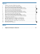
Figure 1 Example of a NonStop NS14000 Series System NonStop NS14000 Series Architecture A NonStop NS14000 series server use Intel® Itanium® processors in duplex or triplex configurations as part of the NonStop NS14000 series architecture. For details of the architecture, see Appendix D (page 103). NonStop NS14000 Series Hardware A large number of enclosure combinations are possible within the modular cabinets of a NonStop NS14000 series server.
Standard hardware for a NonStop NS14000 series server includes: • “NonStop Blade Element” (page 17) • “Logical Synchronization Unit (LSU)” (page 20) • “Versatile I/O (VIO) Enclosure” (page 22) • “Fibre Channel Disk Module (FCDM)” (page 24) • “Maintenance Switch (Ethernet)” (page 24) Optional hardware for a NonStop NS14000 series server includes: • “UPS and ERM (Optional)” (page 25) • “Enterprise Storage System (Optional)” (page 26) • “Tape Drive and Interface Hardware (Optional)” (page 27) A
• I/O interface board, NonStop Blade Element I/O interface board for parallel to serial conversion and maintenance logic (requires removal of enclosure from modular cabinet) • Front panel with indicator LEDs and power buttons The NonStop Blade Element midplane for logic interconnection and power distribution, which is part of the chassis assembly, is not a FRU.
alphanumeric ID, such as A1, A2, A3, and so forth. These IDs refer to the appropriate NonStop Blade Element for proper connection of the fiber-optic cables. The optic cables provide communications between each NonStop Blade Element and the LSU as well as between the LSU and the VIO enclosures on the X fabric and Y fabric. No requirement exists to connect cables from a particular Blade optics adapter on a NonStop Blade Element to a physically corresponding adapter on an LSU.
Front Panel Indicator LEDs LED Indicator State Meaning Power Flashing green Power is on; NonStop Blade Element is available for normal operation. Flashing yellow NonStop Blade Element is in power mode. Off Power is off. Steady amber Hardware or software fault exists. Off NonStop Blade Element is available for normal operation. Flashing blue System locator is activated.
This illustration shows an example LSU configuration as viewed from the front of the enclosure and equipped with four LSU logic boards in positions 50 through 53: LSU Indicator LEDs LED State Meaning LSU optics adapter PIC (green LED) Green Power is on; LSU is available for normal operation. Off Power is off. Amber Power is in progress, board is being reset, or a fault exists. Off Normal operation or powered off.
LED State Meaning Off Power is off, or a fault exists (amber LED is on). Green Power is on with LSU available for normal operation. Off Power is off. LSU logic board PIC (amber LED) Amber Power is in progress, board is being reset, or a fault exists. Off Normal operation or powered off. LSU logic board (green LED) Versatile I/O (VIO) Enclosure NOTE: For NonStop NS14000 series servers that contain I/O Adapter Module (IOAM) enclosures, refer to the H06.
Because each VIO enclosure is a single module, two VIO enclosures are required to provide fault-tolerant paths. The paths must be configured through both VIO enclosures. For example, you could configure these paths through the Fibre Channel ports located on the two VIO enclosures: Path Group Module Slot.Port Primary 100 02 1.1 Primary backup 100 03 1.1 Mirror 100 03 1.2 Mirror backup 100 02 1.2 These paths all exist within the same group.
Fibre Channel Disk Module (FCDM) The FCDM is a rackmounted enclosure that contains: • Up to 14 Fibre Channel arbitrated loop disk drives (enclosure front) • Environmental monitoring unit (EMU) (enclosure rear) • Fibre Channel arbitrated loop (FC-AL) modules (enclosure rear) An FCDM connects to the Fibre Channel ports on a VIO enclosure. You can daisy-chain together up to four FCDMs to reduce the number of Fibre Channel ports required.
Each NonStop NS14000 series system requires multiple connections to the maintenance switch. For more information, refer to the connections described in “Basic LAN Configuration” (page 86) and “Fault-Tolerant Configuration” (page 86). System Console A system console is an HP approved personal computer (PC) running maintenance and diagnostic software for NonStop systems. When supplied with a new NonStop system, system consoles have factory-installed HP and third-party software for managing the system.
This illustration shows the location of an R5500 XR UPS and an ERM in a modular cabinet: For power and environmental requirements, planning, installation, and emergency power-off (EPO) instructions for the HP R5000 UPS or HP R5500 XR UPS, refer to the documentation shipped with the UPS. Enterprise Storage System (Optional) An Enterprise Storage System (ESS) is a collection of magnetic disks, their controllers, and a disk cache in one or more standalone cabinets.
High availability and a fault-tolerant configuration for the Fibre Channel ports on the VIO enclosures are similar to the configurations required for Fibre Channel disk drives, as explained in “VIO Enclosure and Disk Storage Considerations” (page 72).
Preparation for Other Server Hardware This guide provides the specifications only for the NonStop NS14000 series modular cabinet and enclosures identified earlier in this chapter. For site preparation specifications for other HP hardware that will be installed at the site with the NonStop NS14000 series servers, consult with your HP account team. For site preparation specifications relating to hardware from other manufacturers, refer to the documentation for those devices.
Term Definition NonStop Blade Element A physical portion of a logical processor containing up to four processor elements, Each processor element supports a different logical processor numbered 0-7. LSU A component of the system that synchronizes the processor elements of a logical processor and validates all output operations from each processor element before passing the output to the ServerNet fabric.
NonStop Blade Element Group-Module-Slot Numbering • Processor group: 400 through 401 relates to NonStop Blade Complex 0 through 1. Example: group 401 = NonStop Blade Complex 1 • Module: 1 through 3 relates to the processor NonStop Blade Element ID A through C. Example: module 2 = NonStop Blade Element B • Slot: 71 through 78 relates to location of the Blade optics adapter.
LSU Group-Module-Slot Numbering This table shows the default numbering for the LSUs: Item Group (NonStop Blade Complex)1 Module I/O Position (Slot) Individual LSU J set 400 - 401 100 - 107 1 - Optics adapter (rear side, slots 20-27) 2 - Logic board (front side, slots 50-57) Individual LSU K set Not used at this time 1 See “NonStop Blade Element Group-Module-Slot Numbering” (page 30).
VIO Enclosure Group-Module-Slot Numbering A NonStop NS14000 series system supports a single pair of VIO enclosures, identified as group 100: VIO Enclosure Group 100 Module Ports 1-4 Slot X Fabric Y Fabric Displayed by OSM Displayed on Chassis 2 3 1 1 Fibre Channel ports 2 2 Processor ports 1 - 4 (processors 4-7) 3 3 Not supported 4 3 Not supported 5 5 ServerNet cluster ports 1 6 6a Ethernet ports (optical) C and D (10/100/1000 Mbps) 6 6b Ethernet ports (copper) A, B (10/10
Fibre Channel Disk Module Group-Module-Slot Numbering This table shows the default numbering for the Fibre Channel disk module: VIO Enclosure FCDM Group Module Slot Port Shelf Slot 100 2 - X fabric; 3 - Y fabric 1 or 7c 1, 2 1 - 4 if daisy 0 chained); 1 if single disk 1-14 module 89 Item FCDM Disk drives bays Transceiver A1 90 Transceiver A2 91 Transceiver B1 Component Location and Identification 33
VIO Enclosure Group FCDM Module Slot Port Shelf Slot Item 92 Transceiver B2 93 Left FC_AL board 94 Right FC_AL board 95 Left power supply 96 Right power supply 97 Right blower 98 Left blower 99 EMU The form of the GMS numbering for a disk in a Fibre Channel disk module is: This example shows the disk in bay 03 of the Fibre Channel disk module that connects to the Fibre Channel port in the VIO enclosure group 100, module 2, slot 1, port 1: System Installation Document Packet To keep
Configuration Technical Document for the Factory-Installed Hardware Each new NonStop NS14000 series system includes a document called a Technical Document.
2 Site Preparation Guidelines This chapter describes power, environmental, and space considerations for your site. Modular Cabinet Power and I/O Cable Entry Power and I/O cables can enter the Integrity NonStop NS14000 series server from either the top or the bottom rear of the modular cabinets, depending on how the cabinets are ordered from HP and the routing of the AC power feeds at the site.
Power Quality This equipment is designed to operate reliably over a wide range of voltages and frequencies, described in “Enclosure AC Input” (page 59). However, damage can occur if these ranges are exceeded. Severe electrical disturbances can exceed the design specifications of the equipment.
replaced with HP extension bars. The extension bars are oriented inward, facing the components within the cabinet. For complete information and specifications on the HP R5000 UPS or HP R5500 XR UPS, contact your HP representation or refer to the HP UPS R5000 Models User Guide or the HP UPS R5500 XR Models User Guide available at http://h10032.www1.hp.com/ctg/Manual/c00065453.
Weight Because modular cabinets for NonStop NS14000 series servers house a unique combination of enclosures, total weight must be calculated based on what is in the specific cabinet, as described in “Modular Cabinet and Enclosure Weights With Worksheet” (page 62). Flooring NonStop NS14000 series servers can be installed either on the site’s floor with the cables entering from above the equipment or on raised flooring with power and I/O cables entering from underneath.
personnel and lifting or moving devices. If necessary, enlarge or remove any obstructing doorway or wall. All modular cabinets have small casters to facilitate moving them on hard flooring from the unpacking area to the site. Because of these small casters, rolling modular cabinets along carpeted or tiled pathways might be difficult. If necessary, plan for a temporary hard floor covering in affected pathways for easier movement of the equipment.
3 System Installation Specifications All specifications provided in this chapter assume that each enclosure in the modular cabinet is fully populated; for example, a NonStop Blade Element with four processors and maximum memory. The maximum current for each AC service depends on the number and type of enclosures installed in the modular cabinet.
Each single-phase PDU in a modular cabinet has: • 36 AC receptacles per PDU (12 per segment) - IEC 320 C13 12A receptacle type • 3 AC receptacles per PDU (1 per segment) - IEC 320 C19 16A receptacle type • 3 circuit-breakers These PDU options are available to receive power from the site AC power source: • 200 to 240 V AC, single-phase for North America and Japan • 200 to 240 V AC single-phase for International Each PDU distributes the site AC power as single phase 200 to 240 V AC to the 39 outlets
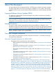
Bottom AC Power Feed, Monitored Single-Phase PDUs Figure 3 shows the AC power feed cables on PDUs for AC feed at the bottom of the cabinet and the AC power outlets along the PDU.
Figure 4 Top AC Power Feed When Optional UPS and ERM are Installed Bottom AC Power Feed When Optional UPS and ERM are Installed If your system includes the optional rackmounted HP R5000 UPS or HP R5500 XR UPS, the modular cabinet will have one PDU located on the rear right side and four extension bars on the rear left side. The PDU and extension bars are oriented inward, facing the components within the modular cabinet.
Figure 5 Bottom AC Power Feed When Optional UPS and ERM are Installed Input and Output Power Characteristics, Monitored Single-Phase PDUs The cabinet includes two monitored single-phase PDUs. North America and Japan: 200 to 240 V AC, Monitored Single-Phase PDUs The North America and Japan PDU power characteristics are: PDU input characteristics • 200 to 240 V AC, single phase, 40A RMS, 3-wire • 50/60Hz • Non-NEMA Locking CS8265C, 50A input plug • 6.
International: 200 to 240 V AC, Monitored Single-Phase PDUs The international PDU power characteristics are: • 200 to 240 V AC, single phase, 32A RMS, 3-wire PDU input characteristics • 50/60Hz • IEC309 3-pin, 32A input plug • 6.
For information about specific characteristics for PDUs factory-installed in monitored three-phase cabinets, refer to • “AC Power Feeds, Monitored Three-Phase PDUs” (page 47) • “Input and Output Power Characteristics, Monitored Three-Phase PDUs” (page 50) • “Branch Circuits and Circuit Breakers, Monitored Three-Phase PDUs” (page 51) Each three-phase monitored PDU in a modular cabinet has: • 36 AC receptacles per PDU (12 per segment) - IEC 320 C13 12A receptacle type • 3 AC receptacles per PDU (1 pe
Figure 6 Top AC Power Feed, Monitored Three-Phase PDUs Bottom AC Power Feed, Monitored Three-Phase PDUs Figure 7 shows the AC power feed cables on PDUs for AC feed at the bottom of the cabinet and the AC power outlets along the PDU.
bars are oriented inward, facing the components within the modular cabinet. To provide redundancy, components are plugged into the left-side PDU and the extension bars. Each extension bar is plugged into the UPS.
Figure 9 Bottom AC Power Feed When Optional UPS and ERM are Installed Input and Output Power Characteristics, Monitored Three-Phase PDUs The cabinet includes two monitored three-phase PDUs. North America and Japan: 200 to 240 V AC, Monitored Three-Phase PDUs The North America and Japan PDU power characteristics are: PDU input characteristics • 200 to 240 V AC, 3–phase delta, 30A, 4-wire • 50/60Hz • NEMA L15-30 input plug • 6.
International: 380 to 415 V AC, Monitored Three-Phase PDUs The international PDU power characteristics are: • 380 to 415 V AC, 3-phase Wye, 16A RMS, 5-wire PDU input characteristics • 50/60Hz • IEC309 5-pin, 16A input plug • 6.
For information about specific characteristics for PDUs factory-installed in modular three-phase cabinets, refer to • “AC Power Feeds, Modular Three-Phase PDUs” (page 52) • “Input and Output Power Characteristics, Modular Three-Phase PDUs” (page 56) • “Branch Circuits and Circuit Breakers, Modular Three-Phase PDUs” (page 57) Each three-phase modular PDU in a modular cabinet has: • 28 AC receptacles per PDU (7 per extension bar) - IEC 320 C13 12A receptacle type • 6 circuit-breakers These PDU optio
Figure 10 Top AC Power Feed, Modular Three-Phase PDUs Bottom AC Power Feed, Modular Three-Phase PDUs Figure 11 shows the power feed cables on modular three-phase PDUs with AC feed at the bottom of the cabinet and the output connections for the three-phase modular PDU.
Figure 11 Bottom AC Power Feed, Modular Three-Phase PDUs Top AC Power Feed When Optional UPS and ERM are Installed If your system includes the optional rackmounted HP UPS, the modular cabinet will have one PDU located on the rear left side and four extension bars on the rear right side. The PDU and extension bars are oriented inward, facing the components within the modular cabinet. To provide redundancy, components are plugged into the left-side PDU and the extension bars.
Figure 12 Top AC Power Feed When Optional UPS and ERM are Installed Bottom AC Power Feed When Optional UPS and ERM are Installed Figure 13 shows the AC power feed cables for the PDU and UPS for AC power feed from the bottom of the cabinet when the optional UPS and ERM are installed. Also see “UPS and ERM (Optional)” (page 25).
Figure 13 Bottom AC Power Feed When Optional UPS and ERM are Installed Input and Output Power Characteristics, Modular Three-Phase PDUs The cabinet includes two modular three-phase PDUs. North America and Japan: 200 to 240 V AC, Modular Three-Phase PDUs and Extension Bars The North America and Japan PDU power characteristics are: PDU input characteristics • 200 to 240 V AC, 3-phase delta, 30A, 4-wire • 50/60Hz • NEMA L15-30 input plug • 12 feet (3.
International: 380 to 415 V AC, Modular Three-Phase PDUs and Extension Bars The international PDU power characteristics are: • 380 to 415 V AC, 3-phase Wye, 16A RMS, 5-wire PDU input characteristics • 50/60Hz • IEC309 5-pin, 16A input plug • 12 feet (3.
Circuit Breaker Ratings for UPS These ratings apply to systems with the optional rack-mounted HP R5000 UPS Integrated UPS that is used for a single-phase power configuration: Version Operating Voltage Settings Power Out (VA/Watts) Input Plug UPS Input Rating1 North America and Japan 200/2082, 220/230/240 5000/4500 L6-30P Dedicated 30 Amp International 200/208/220/2303, 5000/4500 240 If set at 200/208 IEC 60309–32 Amp Dedicated 30 Amp Then 5000/4500 1 The UPS input requires a dedicated (unshar
Enclosure AC Input Enclosures (NonStop Blade Element, VIO enclosure, and so forth) require: Specification Value Nominal input voltage 200/208/220/230/240 V AC RMS 1 Voltage range 180-264 V AC Nominal line frequency 50 or 60 Hz Frequency ranges 47-53 Hz or 57-63 Hz Number of phases 1 1 Voltage range for the VIO enclosure is 100-240 V AC, and for the maintenance switch is 200-240 V AC. Each PDU is wired to distribute the load segments to its receptacles.
Enclosure Type AC Power Lines per Enclosure1 Typical Power Consumption (VA) Maximum Power Consumption (VA) Peak Inrush Current (amps) Rack-mounted system console (NSCR4)4 1 176 176 27 Rack-mounted system console (NSCR110)4 1 105 115 – Rack-mounted keyboard and monitor4 1 28 28 2 M8200-24 Maintenance switch4 1 44 44 4 M8210-24 Maintenance switch4 1 20 20 4 1 2 3 Half of the plugs for an enclosure must be connected to the left-side PDU and the other half connected to the right-
Plan View From Above the Modular Cabinet Service Clearances for the Modular Cabinet Aisles: 6 feet (182.9 centimeters) Front: 3 feet (91.4 centimeters) Rear: 3 feet (91.
Item Height in. Width cm in. Depth cm in. Weight cm with extension, doors, and side panels) Rack 78.5 199.4 23.62 60.0 42.5 108.0 Front door 78.5 199.4 23.5 59.7 3.2 8.1 Left-rear door 78.5 199.4 11.0 27.9 1.0 2.5 Right-rear door 78.5 199.4 12.0 30.5 1.0 2.5 Shipping (palletized) 86.5 219.71 35.75 90.80 54.25 137.80 to “Modular Cabinet and Enclosure Weights With Worksheet” (page 62).
Enclosure Type Number of Enclosures Weight Total lbs kg VIO enclosure 68 30.84 Fibre Channel disk module 78 35.4 Maintenance switch (Ethernet) 4.89 2.22 Rackmount console system unit with keyboard and display 34 15.4 R5000 UPS 126 57 R5000 ERM 139 63 R5500 XR UPS (single-phase power) 160 72.6 R5500 ERM 170 77.1 Total -- -- lbs kg * Modular cabinet weight includes the PDUs and their associated wiring and receptacles.
Heat Dissipation Specifications and Worksheet Enclosure Type Unit Heat (Btu/hour with single AC line powered) Unit Heat (Btu/hour with both AC lines powered) 4-processor NonStop Blade Element with 16 GB memory boards 2320 2594 4-processor NonStop Blade Element 32 GB memory boards 2423 2662 LSU (with four LSU boards) 512 750 VIO enclosure1 893 1112 Fibre Channel disk module2 990 1187 Maintenance switch (Ethernet)3 68 68 Rackmount console system unit with keyboard and display 696 - 1
Nonoperating Temperature, Humidity, and Altitude (except R5000 UPS and R5000 ERM) • Temperature: ◦ Up to 72-hour storage: - 40° to 151° F (-40° to 66° C) ◦ Up to 6-month storage: -20° to 131° F (-29° to 55° C) ◦ Reasonable rate of change with noncondensing relative humidity during the transition from warm to cold • Relative humidity: 10% to 80%, noncondensing • Altitude: 0 to 40,000 feet (0 to 12,192 meters) Nonoperating Temperature, Humidity, and Altitude for R5000 UPS and R5000 ERM • Temperatu
Figure 14 Example Duplex Configuration Table 1 Example Load Calculations for Cabinet One 66 Component Quantity Height (U) Weight (lbs) Weight (kg) Volt-amps, one feed powered Volt-amps, both feeds powered Heat (Btu) NonStop Blade Element 2 10 224 152.4 1420 1560 5324 LSU 1 4 96 43.5 150 220 750 VIO enclosure 2 8 136 61.68 524 652 2224 Fibre 2 Channel disk module 6 156 70.
Table 1 Example Load Calculations for Cabinet One (continued) Component Quantity Height (U) Weight (lbs) Weight (kg) Volt-amps, one feed powered Volt-amps, both feeds powered Heat (Btu) Console - - - - - - - Maintenance 1 switch 1 4.89 2.22 44 - 68 Cabinet 1 42 328 137.4 - - - Total - 42 946 468.
4 System Configuration Guidelines Integrity NonStop NS14000 series systems use a flexible modular architecture. Therefore, almost any configuration of the system’s modular components is possible within a few configuration restrictions stated in “Enclosure Locations in Cabinets” (page 84) and “VIO Enclosure and Disk Storage Considerations” (page 72). NOTE: For NonStop NS14000 series servers that contain I/O Adapter Module (IOAM) enclosures, refer to the H06.
NonStop Blade Elements to LSU Fiber-optic cables provide communications between each NonStop Blade Element and the LSU as well as between the LSU and the VIO enclosure. The ServerNet X fabric and Y fabric provide the system I/O from the LSU to the VIO enclosure, with Fibre Channel and high-speed Ethernet links providing connections to storage and communications LANs, WANs, and so forth.
VIO Enclosure Module Slot.Port Fabric Processor Number 2.3 Y 6 2.4 Y 7 The two cabling diagrams on the next pages illustrate the default configuration and connections for a triplex system processor. These diagrams are not for use in installing or cabling the system. For instructions on connecting the cables, see the NonStop NS14000 Hardware Installation Manual.
VIO Enclosure ServerNet Connections ServerNet connections to the system I/O devices (storage disk and tape drive as well as Ethernet communication to networks) radiate out from the VIO enclosures for both the X and Y ServerNet fabrics. (VIO enclosure module 2 provides X fabric connectivity, and VIO enclosure module 3 provides Y fabric connectivity.) I/O configurations in NonStop NS14000 series systems are flexible, with few restrictions.
Fibre Channel Port to Fibre Channel Disk Modules Fibre Channel disk modules (FCDMs) can be connected directly to the Fibre Channel ports on a VIO enclosure, with these exceptions: • Only configurations with two VIO enclosures are supported. • A maximum of eight FCDMs (or up to eight daisy-chained configurations with each daisy-chain configuration containing 4 FCDMs) can be connected in the NonStop NS14000 series system.
For more information on Fibre Channel ports, see “Versatile I/O (VIO) Enclosure” (page 22). This illustration shows the locations of the hardware in the Fibre Channel disk module as well as the Fibre Channel port connectors at the back of the enclosure: Fibre Channel disk modules connect to Fibre Channel ports on the VIO enclosure via Fiber Channel arbitrated loop (FC-AL) cables.
For more information on the Fibre Channel disk module, see “Fibre Channel Disk Module (FCDM)” (page 24).
Configuration Restrictions for Fibre Channel Devices To avoid creating configurations that are not fault-tolerant or do not promote high availability, these restrictions apply and are invoked by Subsystem Control Facility (SCF): • Primary and mirror disk drives in FCDMs cannot connect to the same Fibre Channel loop. Loss of the Fibre Channel loop makes both the primary volume and the mirrored volume inaccessible. This configuration inhibits fault tolerance.
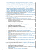
• The NonStop NS14000 series system supports only configurations with two VIO enclosures: ◦ With four Fibre Channel ports and two FCDMs, the primary Fibre Channel port resides in VIO enclosure module 2, and the backup Fibre Channel port resides in VIO enclosure module 3. (See the example configuration in Figure 15 (page 77).
Figure 15 Four Fibre Channel Ports, Two FCDMs, Two VIO Enclosures Fibre Channel Devices 77
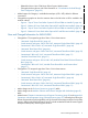
Figure 16 Eight Fibre Channel Ports, Four FCDMs, Two VIO Enclosures 78 System Configuration Guidelines
Figure 17 Twelve Fibre Channel Ports, Six FCDMs, Two VIO Enclosures Fibre Channel Devices 79
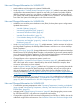
Figure 18 Sixteen Fibre Channel Ports, Eight FCDMs, Two VIO Enclosures Daisy-Chain Configurations When planning for possible use of daisy-chained disks, consider: Daisy-Chained Disks Recommended Daisy-Chained Disks Not Recommended Requirements for Daisy-Chain1 Cost-sensitive storage and applications Many volumes in a large Fibre All daisy-chained Fibre Channel disk using low-bandwidth disk I/O. Channel loop.
1 See “Fibre Channel Devices” (page 72). This illustration shows an example of cable connections between two Fibre Channel ports (one on each VIO enclosure) and four Fibre Channel disk modules in a single daisy-chain configuration: Two VIO enclosures, four Fibre Channel ports, and four Fibre Channel disk modules with an ID expander do not provide fault-tolerant mirrored disk storage.
Ethernet to Networks The Ethernet ports provide Gigabit connectivity between NonStop NS14000 series systems and Ethernet LANs. The Ethernet port is an end node on the ServerNet and uses either fiber-optic or copper cable for connectivity to user application LANs, as well as for the dedicated service LAN. For more information on the Ethernet ports, see “Versatile I/O (VIO) Enclosure” (page 22).
Type of Object Naming Convention Example Description Ethernet connection G group module slot G10027 Ethernet connectivity in location 100.2.7 Ethernet LIF L group module slot port L10027B LIF for PIF at location 100.2.7.0.
5 Hardware Configurations in Modular Cabinets This chapter shows examples of hardware component configurations for the Integrity NonStop NS14000 series server. A number of other configurations are also possible because of the flexibility inherent to the NonStop advanced architecture and ServerNet. NOTE: Hardware configuration drawings in this appendix represent the physical arrangement of the modular enclosures but do not show location of the PDU junction boxes.
6 Maintenance and Support Connectivity Local monitoring and maintenance of the NonStop NS14000 series system occurs over the dedicated service LAN. The dedicated service LAN provides connectivity between the system console and the maintenance infrastructure in the system hardware. HP Insight Remote Support Advanced is the go-forward remote support solution for NonStop servers.
Basic LAN Configuration A basic dedicated service LAN that does not provide a fault-tolerant configuration requires connection of these components to the ProCurve maintenance switch installed in the modular cabinet: • One connection from the ME ENET port on each of the two VIO enclosures • One connection from slot 6B, port A on each of the two VIO enclosure for the OSM Service Connection and OSM Notification Director • One connection to each of the optional UPS modules • One connection for each syste
• Connect one Ethernet port in each VIO enclosure to each maintenance switch. • Connect one maintenance switch to an HP extension bar that is powered by the UPS. HP extension bars are installed in place of a PDU on the rear right side of the modular cabinet. CAUTION: To avoid possible conflicts on the LAN: If the configuration includes two maintenance switches, install and configure one switch completely, including assigning its IP address, before you install the other.
• System consoles • UPSs (optional) These components have default IP addresses that are preconfigured at the factory. You must change these preconfigured IP addresses to addresses appropriate for the LAN environment: Component Group.Module.Slot Default IP Address Used By VIO enclosure 100.2 192.231.36.202 OSM Low-Level Link 100.3 192.231.36.203 Maintenance switch (ProCurve) (rackmounted) N/A 192.231.36.21 N/A 192.231.36.22 Additional switches (rackmounted only) N/A 192.231.36.
Dynamically Assigned IP Addresses Dynamically assigned IP addresses are provided by a DHCP server that assigns an IP address whenever a component is added or moved. If a DHCP server is already present on the network to which these components will be connected, you can use that server. If your network is not equipped with a DHCP server, work with your account team to identify available options.
System-Up Dedicated Service LAN When the system is up and the OS running, the ME connects to the system’s dedicated service LAN using connections from the maintenance switch to ME ENET ports on each VIO enclosure. To use the OSM Service Connection and OSM Notification Director, you must have connections from the maintenance switch to Ethernet ports on each VIO enclosure.
The values in this table show the identification for the Ethernet ports in the preceding illustration: GMS for Ethernet Port Ethernet PIF Location in VIO Enclosure Ethernet LIF TCP/IP Stack IP Configuration 100.2.6b Port A G10026.0.A L1002R $ZTCP0 IP: 192.231.36.10 GW: 192.231.36.9 Subnet: %hFFFFFF00 Hostname: osmlanx 100.3.6b Port A G10036.0.A L1003R $ZTCP1 IP: 192.231.36.11 GW: 192.231.36.
Operating Configurations for Dedicated Service LANs You can configure the dedicated service LAN in several different ways, as described in the OSM Migration and Configuration Guide. HP recommends that you use a fault-tolerant LAN configuration. For a faster configuration option for the OSM Service Connection only, see the OSM Migration and Configuration Guide. System Consoles New system consoles are preconfigured with the required HP and third-party software.
NOTE: Because the system console and maintenance switch are single points of failure that could disrupt access to OSM, this configuration is not recommended for operations that require high availability or fault tolerance. One System Console Managing Multiple Systems The one system console on the LAN must be configured as the primary system console.
A Cables for NS14000 Series Systems Cable Types, Connectors, Length Restrictions, and Product IDs TIP: Although a considerable cable length can exist between the modular enclosures in the system, HP recommends that cable length between each of the enclosures be as short as possible. Available cables and their lengths are: Connection From...
Connection From... Cable Type Connectors Length Product ID VIO enclosure (Fibre Channel port) to: MMF LC-LC 2 meters M8900-02 3m M8900-03 5m M8900-05 6m M8900-06 10 m M8900-10 15 m M8900-15 40 m M8900-40 80 m M8900-80 100 m M8900100 125 m M8900125 200 m M8900200 250 m M8900250 2 meters M8900-02 3m M8900-03 5m M8900-05 6m M8900-06 10 m M8900-10 15 m M8900-15 40 m M8900-40 80 m M8900-80 100 m M8900100 1.5 meters M8926-05 3m M8926-10 4.6 m M8926-15 7.
Cable Management System NonStop NS14000 series systems include the cable management system (CMS) to protect all power, fiber-optic, and CAT 5e or CAT 6 Ethernet cables within the systems. The CMS maintains a 25 millimeter (1 inch) minimum bend radius for the fiber-optic cables and provides strain relief for all cables.
B Operations and Management Using OSM Applications OSM client-based components are installed on new system console shipments and also delivered by an OSM installer on the HP NonStop System Console (NSC) Installer CD. The NSC CD also delivers all other client software required for managing and servicing NonStop NS14000 series servers. For installation instructions, see the NonStop System Console Installer Guide.
AC Power Monitoring For Integrity NonStop NS14000 series servers, you can use one of the following to provide continued system operation through a power failure. However, to take advantage of “OSM Power Fail Support” (page 98), you must use the HP R5000 UPS or HP R5500 XR UPS. When used, it is connected to the system’s dedicated service LAN via the maintenance switch through which OSM monitors the power state.
The actions that OSM takes next are directly tied to that specified ride-through time: • If AC power is restored before the ride-through period ends, the ride-through countdown terminates and OSM does not initiate a controlled shutdown of I/O operations and processors.
NOTE: OSM does not make dynamic computations based on remaining capacity of the rack-mounted UPS. The ride-through time is statically configured in SCF for OSM use. For example, when power comes back before the initiated shutdown, but then fails again shortly afterward, the UPS has been depleted by some amount and does not last for the ride-through time until it is fully recharged. OSM does not account for multiple power failures that occur within the recharge time of the rack-mounted UPS.
C Default Startup Characteristics NOTE: The configurations documented here are typical for most sites. Your system load paths might be different, depending upon how your system is configured. To determine the configuration of your system, refer to the system attributes in the OSM Service Connection. You can select this from within the System Load dialog box in the OSM Low-Level Link.
This illustration shows the system load paths: The command interpreter input file (CIIN) is automatically invoked after the first processor is loaded. The CIIN file shipped with new systems contains the TACL RELOAD * command, which loads the remaining processors. For default configurations of the Fibre Channel ports, Fibre Channel disk modules, and load disks, see “Example Configurations of the VIO Enclosures and Fibre Channel Disk Modules” (page 76).
D NonStop NS14000 Series System Architecture Integrity NonStop NS14000 series systems employ a unique method for achieving fault tolerance in a clustered processor environment, utilizing Intel Itanium microprocessors without cycle-by-cycle lock-stepping. Instead, two or three microprocessors run the same instruction stream concurrently in a loose lockstep process. In loose lockstep: • Each microprocessor runs at its own clock rate.
In the event of a processor fault in either a duplex or triplex processor, the failed component within a NonStop Blade Element (processor element, power supply, and so forth) or the entire Blade Element can be replaced while the system continues to run. A single NonStop NS14000 series system can have up to two NonStop Blade Complexes for a total of eight processors. Processors communicate with each other and with the system I/O over dual ServerNet fabrics.
In summary, these terms describe the NonStop NS14000 series processor: Term Description Processor element (PE) A single Itanium microprocessor with its associated memory. A PE is capable of executing an individual instruction stream and I/O communication through fiber-optic links. NonStop Blade Element Two or four PEs contained within a single NonStop Blade Element enclosure. Logical processor One or more PEs from each NonStop Blade Element executing a single instruction stream.
Triplex Processor The TMR or triplex processor uses three NonStop Blade Elements, A, B, and C. As with the duplex processor, the fiber-optic cables connect the PEs to the LSUs, and these LSUs then connect to the two independent ServerNet fabrics via the VIO enclosure. Dual ServerNet fabrics create communications redundancy in case one of the fabrics fails. For a description of the LSU functions, see “Processor Synchronization and Rendezvous” (page 107).
In a TMR or triplex processor, each LSU has inputs from three PEs. As with the duplex processor, the LSU keeps the three PEs in loose lockstep. The triplex processor provides fault tolerance upon failure of a PE by comparing the output from the three NonStop Blade Elements to determine which one is errant. This method eliminates the question of which output is valid when two outputs disagree in a duplex system.
memory and processor states be copied from a functioning PE to the target PE. Once the memory and processor state data is copied, rendezvous is used to complete the reintegration. This entire reintegration operation is invisible to the running applications. Failure Recovery for Duplex Processor Duplex processors have no single points of failure. Any single element of a duplex processor might fail, but alternative paths exist for operation of user applications.
Index Symbols $SYSTEM disk locations, 101 A AC current calculations, 65 AC power enclosure input specifications, 59 input, 42, 47, 52 power-fail monitoring, 98 power-fail states, 100 unstrapped PDU, 58 AC power feed bottom of cabinet, 43, 48, 53 modular three-phase, 52 monitored single-phase, 42 monitored three-phase, 47 top of cabinet, 42, 47, 53 with cabinet UPS, 43, 44, 48, 49, 54, 55 air conditioning, 38 air filters, 39 airflow direction through enclosures, 65 B branch circuit, 46, 51, 57 Btu/hour, en
configurations, 74 recommendations, 75 supported for internal use, 72 Fibre Channel disk module, 24, 72 Fibre Channel port to FCDM cabling, 76 Fibre Channel port to tape cabling, 72 flooring, 39 forms for ServerNet adapter configuration, 35 front panel, NonStop Blade Element buttons, 19 indicator LEDs, 20 FRU AC power assembly, LSU, 20 fan, NonStop Blade Element, 17 Fibre Channel disk module, 24 I/O interface board, 18 logic board, LSU, 20 memory board, 17 optic adapter, LSU, 20 optic adapter, NonStop Blade
power supply NonStop Blade Element, 17 VIO enclosure, 22 power-fail monitoring, 98 states, 100 processor board, FRU, 17 complex, 28, 103 default numbering, 30 elements, 103, 105 interconnect cabling, 69 synchronization, rendezvous, 107 processor ID, 18 ProCurve maintenance switch, 24 R rack, 28 rack offset, 28, 29 raised flooring, 39 receive and unpack, 39 receptacles, PDU, 41 recovery, failure, 108 reintegration board, 17 reintegration, memory, 107 rendezvous, processor synchronization, 107 restrictions c