
NonStop NS16000 Series Planning Guide (H06.11+)


The NonStop Blade Element midplane for logic interconnection and power distribution, which is
part of the chassis assembly, is not a FRU.
Two NonStop Blade Elements provide up to four processor elements in a high-availability duplex
configuration, and eight NonStop Blade Elements provide a full 16-processor duplex system. For
a fault-tolerant triplex system, three NonStop Blade Elements provide four processors, and 12
NonStop Blade Elements provide a full 16-processor triplex system.
NOTE: Integrity NonStop NS16000 series systems do not support duplex and triplex processors
within the same system.
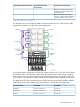
This illustration shows the rear of the NonStop Blade Element, equipped with two power supplies
and eight Blade optics adapters:
The numbers below the optics connectors refer to the processor numbers within the NonStop Blade
Element enclosure. Currently, only connectors J0, J1, J2, and J3 are used. The remaining J connectors
are for future use by the NonStop Blade Element hardware.
CAUTION: To maintain proper cooling air flow, blank panels must be installed in all slots that
do not contain Blade optics adapters.
Labels for the fiber-optic cable connections can become complex in a large system. Fiber-optic
cables for the ServerNet fabric and also the optic cable connections use the same type of optics
connector.
Because the modular hardware provides considerable flexibility in how the hardware is distributed
among multiple cabinets, a single cabinet could contain four NonStop Blade Elements, with each
NonStop Blade Element a member of a different NonStop Blade Complex.
To reduce ambiguity in identifying proper cable connections to the NonStop Blade Complex, the
identification convention uses combinations of a letter to refer to each connection. A number such
as 0, 1, 2, and 3 identifies NonStop Blade Complexes, and a letter such as A, B, or C identifies
the NonStop Blade Element. Therefore, a single NonStop Blade Element is identified with an
alphanumeric ID, such as A1, A2, A3, and so forth. These IDs refer to the appropriate NonStop
Blade Element for proper connection of the fiber-optic cables.
The optic cables provide communications between each NonStop Blade Element and the LSU as
well as between the LSU and the p-switch PICs on the X fabric and Y fabric. No requirement exists
to connect cables from a particular Blade optics adapter on a NonStop Blade Element to a physically
corresponding adapter on an LSU. However, to help reduce the complexity of cable connections,
108 Modular System Hardware