
NonStop Operations Guide for H-Series and J-Series RVUs

3. To physically monitor power-on activity:
a. Check fan activity for all of the following that are present in your NonStop system: c7000
enclosure, NonStop server blades, processor switches, processor Blade Elements, CLIMs,
IOAM or VIO enclosures, and FCDM enclosures. Check that the fans are turning and that
you can feel air circulate through the components.
b. After the POSTs finish, check that only green power-on LEDs are lit in the system
components before you start the system. For more information about status LEDs, see
“Using the Status LEDs to Monitor the System ” (page 68).
4. After the POSTs finish, check the AC power cords. Perform this test only if you have connected
redundant power cords to separate circuits:
a. If you have a UPS installed, switch off the UPS outputs.
b. If you do not have a UPS installed:
a. Locate the circuit breaker that controls half the power cords.
b. Switch this breaker off.
c. Check that all components are still operating.
NOTE: The maintenance switch does not have redundant power.
d. Switch this breaker back on.
e. Locate the other circuit breaker that controls the other half of the power cords.
f. Switch this breaker off.
g. Check that all components are still operating.
h. Switch this breaker back on.
i. If any components fail during any of the power shutdowns, see “Components Fail When
Testing the Power ” (page 194).
j. If you have a UPS installed, switch off the UPS outputs.
5. If you have a UPS installed, check that the UPS is fully charged. Then, test the UPS by turning
off both circuit breakers.
6. Log on to the OSM Low-Level Link.
7. Select System Discovery.
8. Double-click the System.
9. Double-click each Group 40n; for example, Group 400 in NonStop NS-series systems. For
NonStop BladeSystems, logical processors down are displayed in Module 1 of their group,
and there is no Group 400.
10. Check that the logical processors are displayed.
11. Double-click each Group 1nn; for example, Group 100.
12. For each Group 1nn, check that module 2 and module 3 are displayed.
13. If any of these components are not yet displayed, wait before you start the system.
For NonStop BladeSystems and NonStop NS2400 series, NS2300, NS2200 series, NS2100,
and NS2000 series systems, verify that all the processors have come up, as follows:
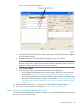
a. Close the current OSM Low-Level Link session, then launch and log on to a new session.
b. On the OSM Low-Level Link toolbar, click the Processor Status button to display the OSM
Low-Level Link Processor Status dialog box.
178 Starting and Stopping the System