
RDF System Management Manual for H-Series and J-Series RVUs (RDF 1.9)
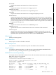
($RRCV0) associated with the MAT and writing to the Master Image Trail ($MIT) and a Secondary
Image Trail ($IMAGE0), a second receiver ($RRCV1) associated with AUX01 and writing to a
Secondary Image Trail ($IMAGEA1), updater $RUPD1 associated with the MAT reading $IMAGE0
and applying updates to $DATA006, updater $RUPD2 associated with the AUX01 reading
$IMAGEA1 and applying updates to $DATA007, and updater $RUPD3 associated with the
AUX01 reading $IMAGEA1 and applying updates to $DATA08.
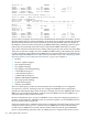
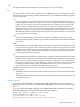
The second example above shows the same configuration, but this time in the midst of an RDF
takeover operation.
In both examples, different state information is displayed for each entity under the different
column headings.
RDF Process
The first column of the display identifies the type of process. Notice that each updater process
is identified by the names of both the primary volume the updater process is protecting and the
corresponding volume on the backup system. In this example, each volume being updated on
the backup system has the same name as the corresponding volume on the primary system (for
example, updates to the volume $DATA007 on the primary system are duplicated by the updater
process $RUPD2 to the volume $DATA007 on the backup system).
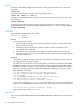
Name
The second column specifies the name of each process. Because the secondary image trails
$IMAGE0 and $IMAGEA1 are not processes, they do not have process names or RTD times. In
the second example above, observe that the monitor no longer has the configured process name.
The reason for this is that the monitor started on the backup system for a takeover operation is
started with a Guardian-generated name.
RTD Time
The third column (labeled RTD Time) specifies the current relative time delay (RTD) value for
the extractor process, receiver process, and all updater processes. These values can help you
determine how far behind the application program each process is running. Please note that an
RTD time is not a precise indication of how far an RDF process is behind. An RTD time is only
relative and is an approximation. The more accurate RTD time is that of the extractor. An updater's
RTD is even more relative because it may show 20 seconds one instance and then show 0 seconds
in the next instance. The reason for this is that the updater applies audit through an exceptionally
efficient low-level interface direct to the disk process and it can take only a fraction of 1 second
to apply what was generated on the primary system in 20 seconds.
On the primary system, TMF attaches a timestamp to every commit and abort status record
generated for the application program. The extractor process, in turn, attaches the most recent
TMF commit/abort timestamp to all data modification image records.
The RTD value for the master extractor is the difference between the “last modified time” of the
latest file in the TMF Master Audit Trail (MAT) and the timestamp of the last commit or abort
record seen by this extractor. For an extractor associated with an aux trail, its RTD value is the
difference between the “last modified time” of the latest file in the specific audit trail and the
general time when the last audit record processed by this extractor was added to this audit trail.
As each receiver processes image records, it stores them in image trail buffers and writes those
buffers to disk as the need arises. The receiver's RTD only has value on a receiver restart condition
(for example, primary CPU failure), where the receiver process has had to go to disk to get its
context and then begin operations anew, just as if it were just started by RDFCOM. The RTD
reflects only how long it takes to complete its restart, and in this sense a receiver's RTD has no
consequence because the extractor's RTD is of critical importance. In the takeover situation
reflected in the second example, the RTD is replaced by dots to indicate there is no RTD.
RDFCOM Commands 247