
Cluster I/O Protocols (CIP) Configuration and Management Manual (H06.16+, J06.05+)


customer data. (However, the Telco CLIM only supports copper Ethernet interfaces.) Another, built-in
Ethernet interface can also be used for customer data.
See the system planning guide for your system for more information about where the CLIM fits into
your NonStop system. For carrier grade CLIMs, contact your service provider for more information.
NOTE: The CLIM is intended only for the NonStop host system I/O functionality described in this
manual. HP does not support any other use of the CLIM. Any other use of the CLIM, including
installation of any unauthorized software, voids the warranty. In particular, do not attempt to install
customer code or any customer-originated Linux utilities within the CLIM.
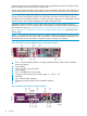
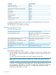
The physical Ethernet interfaces on the CLIM include two built-in Ethernet interfaces and four
additional ones in one or two expansion PICs. The interfaces are named by the CLIM kernel from
top to bottom as shown in Figure 8: DL385 G2 or G5 IP CLIM Interfaces, Five Copper Interfaces
(page 52) or Figure 9: DL380 G6 IP CLIM, Five Copper Interfaces (page 52), depending on the
CLIM's model.
NOTE: In this manual, for IP CLIM and IP CIP, “interface” refers to the Ethernet port in the network
interface card (NIC). The term “port” refers to the UDP or TCP number present in the header of a
data packet and used to map data to a particular process running on a computer.
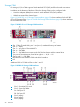
Figure 8 DL385 G2 or G5 IP CLIM Interfaces, Five Copper Interfaces
1
Slot 1. Customer-usable interfaces: 4 copper Ethernet interfaces, eth2 to eth5, numbered
from top to bottom
2
Slot 2 (empty)
3
Slot 3: two pair of ServerNet PICs
4
Slot 4 (empty)
5
Slot 5: SAS HBA for the internal disk
6
Two pair of ServerNet ports, from left to right: A — YX, B — YX
7
SAS HBA
8
eth1 customer-usable interface
9
Maintenance LAN interface. Eth0 and eth0:0 interface
10
ILO
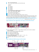
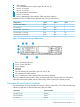
Figure 9 DL380 G6 IP CLIM, Five Copper Interfaces
52 Overview