
Cluster I/O Protocols (CIP) Configuration and Management Manual (H06.16+, J06.05+)
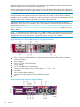

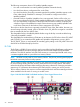
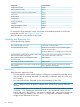

1
Slot 1: ServerNet PCIe card
2
Slot 2: 2-port network interface card, from left to right:
2A: eth 4
2B: eth 5
3
Slot 3 (empty)
4
Slot 4 (empty)
5
Slot 5 (empty)
6
Slot 6 (empty)
7
Four ServerNet ports, from left to right: XB, YB, XA, YA
8
LAN 4: eth 3 customer-usable interface
9
LAN 3: eth 2 customer-usable interface
10
ILO: Maintenance LAN interface
11
LAN 2: eth 1 customer-usable interface
12
LAN 1: Maintenance LAN interface. Eth0 and eth0:0 interface
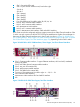
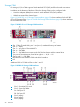
An IP CLIM can also be configured with three copper ports and two Fibre Channel interfaces. Slots
2 and 4 can each contain one HP NC373F PCI Express Multifunction Gigabit Server Adapter. In
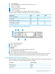
that case, the Fibre Channel interfaces are in slots 2 and 4 as show in Figure 10: DL385 G2 or
G5 IP CLIM Interfaces, Three Copper, Two Fiber Channel Interfaces (page 53) or Figure 11: DL380
G6 IP CLIM Three Copper, Two Fiber Interfaces (page 53), depending on the CLIM's model.
Figure 10 DL385 G2 or G5 IP CLIM Interfaces, Three Copper, Two Fiber Channel Interfaces
1
Slot 1: Customer-usable interface: 2 copper Ethernet interfaces, eth2 and eth3, numbered
from top to bottom
2
Slot 2: eth5 fibre channel customer-usable interface
3
Slot 3: two pair of ServerNet PICs
4
Slot 4: eth4 customer-usable interface
5
Slot 5: SAS HBA for the internal disk
6
Two pair of ServerNet ports, from left to right: A — YX, B — YX
7
eth1 customer-usable interface
8
Maintenance LAN interface. Eth0 and eth0:0 interface
9
ILO
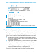
Figure 11 DL380 G6 IP CLIM Three Copper, Two Fiber Interfaces
The CIP Subsystem for Internet Protocols (IP CIP) 53