
Expand Configuration and Management Manual (H06.21+, J06.10+)


Tuning
Expand Configuration and Management Manual — 529522-013
19 - 20
Network Topology
load factor to each other line handler and predict the resulting change in load
factors.
Choose the single move that results in the lowest predicted load factor spread, put
it on the output change list, update the load factors according to the predicted
changes, and check the new load factor spread value. This is continued until the
load factor spread is less than 0.5 or no moves can be found that improve the load
factor spread.
3. Lastly, the pair counts are balanced. Use the path selection algorithm described
above with current ETF information to determine the goal number of pairs for each
line handler. To prevent new line handlers with low ETFs and no current pairs from
taking on more pairs than they can actually handle, those line handlers with too few
pairs have their goals reduced by half their shortfall.
Then consider moving each pair from the line handler with the highest excess pairs
to each line handler with a dearth. Choose the move that results in the lowest
predicted load-factor spread with no increase from previous efforts. If more than
one path has the same lowest load-factor spread, choose the one with the largest
pair-count shortfall. This is continued until there are no excess pairs or all possible
moves increase the load-factor spread.
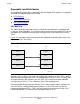
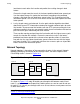
Network Topology
Network topology is the pattern of interconnection of nodes in the network. Network
topology, particularly the location of passthrough nodes, can affect response time.
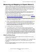
Passthrough traffic is shown in Figure 19-5.
As shown in Figure 19-5, node \B handles passthrough traffic between node \A and
node \C, so it must have two Exp
and line-handler processes: one for node \A and one
for node \C. As a result, passthrough traffic uses at least twice as much processor time
as does direct traffic.
Figure 19-5. Passthrough Traffic
Note. The advantages and disadvantages of different network topologies are discussed in
Section
3, Planning a Network Design.
Node \A Node \B
Node \C
$LINEB $LINEA $LINEC $LINEB
VST049.vsd