
Expand Configuration and Management Manual (H06.21+, J06.10+)


Planning a Network Design
Expand Configuration and Management Manual — 529522-013
3 - 15
Creating a Network Diagram
Creating a Network Diagram
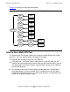
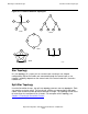
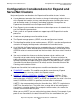
Before you configure your Expand network, HP recommends that you create a diagram
of the complete network topology. This network diagram shows the network nodes and
the lines that connect the nodes. This type of diagram can help you and the operations
staff monitor systems, recognize problems, and prepare for configuration changes.
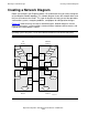
Figure 3-5 shows one way to create a network diagram. Network diagrams should
show system names, system numbers, communications hardware device names, and
Expand line-handler process names.
Note. System names and numbers are configured through the SCF interface to the NonStop
operating system subsystem (see the SCF Reference Manual for the Kernel Subsystem).
Figure 3-5. Network Diagram
VST030.vsd
SWAN
SWAN
SWAN SWAN
SWAN
$PATH1
$LINE1
$LINE2
$LINE3
$PATH1
$LINE1
$LINE2
$LINE3
$LINEA $LINEB
$LINEC $LINEC
\LA
Node1
\DALLAS
Node 2
\BOISE
Node 3
\CHICAGO
Node 4
$LINEA
$LINEB
SWANSWAN
SWAN