
NonStop NS2200 Series Planning Guide


6 Hardware Configuration in NonStop NS2200 Cabinets
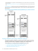
This section shows locations of hardware components within 36 and 42U modular cabinets for a
NonStop NS2200 commercial system.
NOTE: Hardware configuration drawings in this section represent the physical arrangement of
the modular enclosures but do not fully show PDUs. For information about PDUs, see “Power
Distribution for NonStop NS2200 Systems In Intelligent Racks” (page 56).
Maximum Number of Modular Components, NonStop NS2200 System
This table shows the maximum number of the modular components installed in an NS2200 system.
These values might not reflect the system you are planning and are provided only as an example,
not as exact values.
NonStop NS2200 systemEnclosure or Component
1
4-processor2-processor
42Blade element (rx2800 i2)
11System console
22VIO enclosure
44Storage CLIM
22IP CLIM
22Telco CLIM
11CLIM patch panel
84SAS disk enclosure
22Maintenance switch
11HP R5000 or R5500 XR UPS (for
single-phase)
11HP R12000/3 UPS (for three-phase)
22Extended runtime module (ERM) (for
single-phase)
22ERM (for three-phase)
1
See “IP and Telco CLIM Coexistence Limits ” (page 103) for information about coexistence limits for IP and Telco CLIMs.
IP and Telco CLIM Coexistence Limits
Your NonStop NS2200 system supports the following combinations of IP and Telco CLIMs:
CLIM Coexistence Limits
6 Supported Combinations
Telco CLIMIP CLIM
00
01
10
11
Maximum Number of Modular Components, NonStop NS2200 System 103