
NonStop NS2400 Series Planning Guide
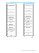


Figure 34 HP M8391-24x and M8392-24x Disk Enclosure, Back View
Connect SAS In Port (on the left) for each module to the Storage CLIM. Out Port is not used.
Fuse Panel
NOTE: For your safety, there are procedures to observe when working with the fuse panel. For
these procedures, ask your HP service provider to refer to the NonStop NS2200 Series and
NS2400 Series Hardware Installation Manual.
The fuse panel (Figure 35) fuse panel requires 2U of space. The fuses are accessed from the front
of the cabinet. Power cabling is accessed from the rear of the cabinet.
The fuse panel has a current rating of 80A. It accepts power from both power rails and distributes
it to four individually fused TPA outputs and to five individually fused GMT outputs per rail. GMT
outputs are rated up to 15A. TPA outputs are rated up to 50A. Power cables from enclosures that
receive power from the fuse panel connect to the outputs on the rear of the fuse panel (Figure 35).
This fuse panel is the same fuse panel used in NonStop NS-Series Carrier-Grade Servers, but uses
fuses of different sizes.
Figure 35 Fuse Panel
CG Maintenance Switch
The CG maintenance switch provides the communication between the NonStop NS2400T and
NS2400ST systems through the VIO enclosures, CLIM CGs, and the desktop system console running
or accessing OSM software.
110 NonStop NS2400T and NS2400ST Systems Overview