
RDF System Management Manual for H-Series RVUs (RDF 1.8)
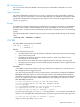
For extractors, receivers, and image trails, the configured ATINDEX value is displayed in
parentheses following the object name. In the above example, the extractor $RE00 and receiver
$RR00 are associated with the MAT, while the extractor $RE01 and receiver $RR01 are associated
with auxiliary audit trail AUX01.
Because of insufficient space, however, ATINDEX values could not be displayed explicitly for
updaters. To determine the ATINDEX value of a particular updater, see the ATINDEX value of
the associated secondary image trail.
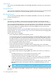
In this example, a monitor process and two extractor processes are configured on the primary
system, and two receiver processes and three updater processes are configured on the backup
system. For each process, these items appear, indicated by column headings near the top of the
display:
RDF Process
The first column of the display identifies the type of process. Notice that each updater process
is identified by the names of both the primary volume the updater process is protecting and the
corresponding volume on the backup system. In this example, each volume being updated on
the backup system has the same name as the corresponding volume on the primary system (for
example, updates to the volume $DATA07 on the primary system are duplicated by the updater
process $RU02 to the volume $DATA07 on the backup system).
Name
The second column specifies the name of each process.
RTD Time
The third column (labeled RTD Time) specifies the current RDF time delay (RTD) value for the
extractor process, receiver process, and all updater processes. These values can help you determine
how far behind the application program each process is running.
On the primary system, TMF attaches a timestamp to every commit and abort status record
generated for the application program. The extractor process, in turn, attaches the most recent
TMF commit/abort timestamp to all data modification image records.
The RTD value for each extractor is the difference between the “last modified time” of the TMF
Master Audit Trail (MAT) and the timestamp in the most recent image record processed by that
extractor.
As each receiver processes records, it writes them to a buffer and then moves them from the
buffer as the need arises. Each receiver keeps track of the last audit record it wrote to disk at the
last save point; if the receiver must restart because the primary system goes down, this save point
becomes the receiver’s restart point. The RTD for a receiver is the difference between the “last
modified time” of the TMF MAT and the timestamp that identifies the associated restart point.
The RTD value reported for each updater process is the difference between the “last modified
time” of the TMF Master Audit Trail (MAT) and the timestamp in the most recent image record
seen by the particular updater.
The RTD value reflects, in the most general sense, the amount of time by which the backup
database is lagging behind the primary database. In the example shown in “STATUS RDF
Command Output Display” earlier in this command description, the specified RTD time for the
updater $RU03 is 0 minutes and 6 seconds, meaning that the updater is running approximately
6 seconds behind the MAT.
On a finely tuned RDF backup node, the RTD for an updater can regularly lag 1 to 15 seconds
behind TMF processing. However, this 15-second delay does not mean that 15 seconds are needed
to catch up; that operation might take only a few seconds.
If RDFCOM cannot connect to a particular process, RDFCOM displays dots (...) in the RTD Time,
Sequence, and Rel Byte No fields, and an appropriate file-system error number in the Error field.
232 Entering RDFCOM Commands