
Enclosure Interleaving Disk Configuration

Enclosure Interleaving Disk Configuration 5/21/04
Hewlett-Packard Development Company L.P. Page 2 of 8 CSSI Website
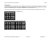
Configurations:
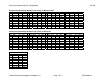
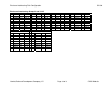
These diagrams show the configurations that are shipped when the Enclosure Interleaving disk configuration is ordered. All
possible combinations of enclosures are shown for topology branch 1 (Groups 1 and 11-15) and topology branch 2 (Groups
2 and 21-25). Topology branches 3 and higher are configured the same as topology branch 2.
If you have questions regarding the information in this document, contact the Global Customer Support Center (GCSC).
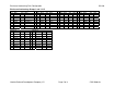
Enclosure Interleaving: Group 1, no Groups 11-15
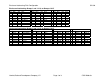
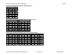
Enclosure Interleaving: Group 1 and 11, no Groups 12-15
Group 1 Group 11
Slot Disk Slot Disk Slot Disk Slot Disk
1 $E-P 11 $SYSTEM-P 1 $N-P 11 $I-P
2 $N-M 12 $SYSTEM-M 2 $E-M 12 $I-M
3 $F-P 13 $DSM-P 3 $O-P 13 $J-P
4 $O-M 14 $J-M 4 $F-M 14 $DSM-M
5 $G-P 15 $AUDIT-P 5 $Q-P 15 $K-P
6 $Q-M 16 $K-M 6 $G-M 16 $AUDIT-M
7 $H-P 17 $OSS-P 7 $R-P 17 $L-P
8 $R-M 18 $L-M 8 $H-M 18 $OSS-M
Group 1
Slot Disk Slot Disk
1 $E-P 11 $SYSTEM-P
2 $F-P 12 $SYSTEM-M
3 $G-P 13 $DSM-P
4 $H-P 14 $AUDIT-P
5 $F-M 15 $OSS-P
6 $G-M 16 $DSM-M
7 $H-M 17 $AUDIT-M
8 $E-M 18 $OSS-M