OSM Alarm Summary Abstract: The purpose of this document is to present a list of all HP NonStop™ Open System Management (OSM) alarms that might be created and displayed in the OSM Service Connection. This document is divided into two sections: • OSM alarms that apply to all HP NonStop servers (G06.28 (OSM T0682G07^AAL) & later and H06.05 (OSM T0682 H02 AAN) & later) • OSM alarms unique to HP Integrity NonStop NS-series servers (H06.05 (OSM T0682 H02 AAN) & later) Last Updated: 04/19/2007 Alarm 1.
Table of Contents Section 1 OSM Alarms Common to HP NonStop Servers 1.1 1.2 1.3 1.4 1.5 1.6 1.7 1.8 1.9 1.10 1.11 1.12 1.13 1.14 1.15 1.16 1.17 1.18 1.19 1.20 1.21 1.22 1.23 1.24 1.25 1.26 1.27 1.28 1.29 1.30 1.31 1.32 1.33 1.34 1.35 1.36 1.37 1.38 1.39 1.40 1.41 1.42 1.43 1.44 1.45 1.46 1.47 1.48 1.49 1.50 1.51 1.52 1.53 1.54 1.55 1.56 1.57 1.58 1.
1.60 1.61 1.62 1.63 1.64 1.65 1.66 1.67 1.68 1.69 1.70 1.71 1.72 1.73 1.74 1.75 1.76 1.77 1.78 1.79 1.80 1.81 1.82 1.83 1.84 1.85 1.86 1.87 1.88 1.89 1.90 1.91 1.92 1.93 1.94 1.95 1.96 1.97 Switch 1.98 1.99 1.100 1.101 1.102 1.103 1.104 1.105 1.106 1.107 1.108 1.109 1.110 1.111 1.112 1.113 1.114 1.115 1.116 1.117 1.118 1.119 1.120 1.121 1.
1.123 1.124 1.125 1.126 1.127 1.128 1.129 1.130 1.131 1.132 1.133 1.134 1.135 1.136 1.137 1.138 1.139 1.140 1.141 1.142 1.143 1.144 1.145 1.146 1.147 1.148 1.149 1.150 1.151 1.152 1.153 1.154 1.155 1.156 1.157 1.158 1.159 1.161 1.162 1.163 1.164 1.165 1.166 1.167 1.168 1.169 1.170 1.171 1.172 1.173 1.174 1.175 1.176 1.177 1.178 1.179 1.180 1.181 1.182 1.183 1.184 1.185 1.186 1.
1.188 1.189 1.190 1.191 1.192 1.193 1.194 1.195 1.196 1.197 1.198 1.199 1.200 1.201 1.202 1.203 1.204 1.205 1.206 1.207 1.208 1.209 1.210 1.211 1.212 1.213 1.214 1.215 1.216 1.217 1.218 1.219 1.220 1.221 1.222 1.223 1.224 1.225 1.226 1.227 1.228 1.229 1.
2.19 2.20 2.21 2.22 2.23 2.24 2.25 2.26 2.27 2.28 2.29 2.30 2.31 2.32 2.
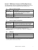
Section 1 OSM Alarms Common to HP NonStop Servers This section describes OSM alarms that apply to all HP NonStop servers on G06.28 (OSM T0682G07^AAL) & later and H06.05 (OSM T0682 H02 AAN) & later. 1.
1.4 Fault State Alarm Field Possible Values Resource Type Enclosure Fan/ Enclosure Battery Dials Out Yes Perceived Severity Major This alarm indicates a hardware problem with the corresponding enclosure fan or enclosure battery. 1.
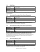
1.8 Uncorrectable Memory Error Alarm Field Possible Values Resource Type CPU Dials Out Yes Perceived Severity Major This alarm indicates that the processor is hung on account of an uncorrectable memory error. 1.9 Hardware Error Freeze Alarm Field Possible Values Resource Type CPU Dials Out Yes Perceived Severity Critical This alarm indicates that a hardware error freeze occurred on the processor. The repair text contains the specific incident details. 1.
1.12 No Memory Alarm Field Possible Values Resource Type CPU Dials Out Yes Perceived Severity Major This alarm indicates that there is no memory installed on this processor. 1.13 SCSI Boot Code Update Failure Alarm Field Possible Values Resource Type CPU Dials Out Yes Perceived Severity Major This alarm indicates that the processor has undergone a %100240 halt. The SCSI boot code firmware has not been loaded. 1.
1.16 Missing Power Monitor and Control Unit Alarm Field Possible Values Resource Type PMCU Dials Out Yes Perceived Severity Major/Critical This alarm indicates that the system could not detect a required PMCU Cru. The exact location is part of the repair text of the alarm. 1.17 Missing Fan Alarm Field Possible Values Resource Type Enclosure Fan/ Switch 3 Fan Dials Out Yes Perceived Severity Major/Critical This alarm indicates that the system could not detect a required fan CRU.
1.20 Unknown CRU Alarm Field Possible Values Resource Type Any Enclosure CRU Dials Out Yes Perceived Severity Minor This alarm indicates that the system could not detect the Cru type. The exact location is part of the repair text of the alarm. 1.
1.24 ASIC Freeze Error Alarm Field Possible Values Resource Type Any Enclosure CRU Dials Out Yes Perceived Severity Major This alarm indicates that the service processor (SP) has detected a self check error condition on an ASIC in the CRU. 1.25 Invalid Power Measurement Alarm Field Possible Values Resource Type PMCU Dials Out Yes Perceived Severity Minor This alarm indicates that an invalid power measurement has been detected in the PMCU CRU. 1.
1.28 Temperature Out of Limits Alarm Field Possible Values Resource Type PMCU/Disk Dials Out Yes Perceived Severity Critical This alarm indicates that the temperature of the resource is out of limits. 1.29 Down-rev MSEB NNA PIC Alarm Field Possible Values Resource Type External Fabric Dials Out Yes Perceived Severity Critical This alarm indicates that the NNA PIC in connector 6 of the Modular ServerNet Expansion Board (MSEB) in group 1, module 1, slot 51|52 is down-rev. 1.
1.32 Node Plugged into Wrong Port of ServerNet Switch Alarm Field Possible Values Resource Type External Fabric Dials Out Yes Perceived Severity Major This alarm indicates that the node is plugged in to the wrong port of the ServerNet switch. 1.
1.36 Invalid MSEB Configuration Record Alarm Field Possible Values Resource Type External Fabric Dials Out Yes Perceived Severity Minor This alarm indicates that the SANMAN process found an invalid configuration record for the Modular ServerNet Expansion Board (MSEB) in group 1, module 1, slot 51|52. 1.
1.40 IBC Driver Limit of ServerNet Switches Exceeded Alarm Field Possible Values Resource Type Enclosure Fan/ Enclosure Battery Dials Out Yes Perceived Severity Major This alarm indicates that the number of the ServerNet switches that the IBC driver can support has been exceeded for the external fabric. 1.
1.44 SMC Driver Unable to Obtain Locked Memory Alarm Field Possible Values Resource Type External Fabric Dials Out Yes Perceived Severity Major This alarm indicates that the SMC driver could not obtain the locked memory to satisfy a SANMAN request. The primary SANMAN processor may be running low on memory resources. 1.
1.48 ServerNet Path Down in Group , Module 1, Slot Alarm Field Possible Values Resource Type Internal Fabric Dials Out Yes Perceived Severity Critical This alarm indicates that ServerNet path between the router and the processor in the group , module 1, slot is down. The exact reason is part of the repair text. 1.
1.52 Automatic Redundant Power Scrub Test Not Run Alarm Field Possible Values Resource Type System Dials Out No Perceived Severity Critical This alarm indicates that the automatic redundant power scrub test was not run because a ServerNet Path Test Failed alarm exists on the internal ServerNet Fabric. 1.
1.56 Firmware Stuck in a Transient State Alarm Field Possible Values Resource Type Switch 3 LB Dials Out Yes Perceived Severity Major This alarm indicates that the firmware on the switch logic board has been in a transient state for five minutes indicating a problem. 1.
1.60 CRC Error in Firmware Image A Alarm Field Possible Values Resource Type Switch 3 LB Dials Out Yes Perceived Severity Major This alarm indicates that a CRC error has been detected on firmware image A of the switch logic board. 1.61 CRC Error in Firmware Image B Alarm Field Possible Values Resource Type Switch 3 LB Dials Out Yes Perceived Severity Major This alarm indicates that a CRC error has been detected on firmware image B of the switch logic board. 1.
1.64 CRC Error in Configuration Image B Alarm Field Possible Values Resource Type Switch 3 LB Dials Out Yes Perceived Severity Major This alarm indicates that a CRC error has been detected on configuration image B of the switch logic board. 1.
1.68 Mismatch in Versions of Two FPGA Images Alarm Field Possible Values Resource Type Switch 3 LB Dials Out Yes Perceived Severity Major This alarm indicates that the VPROCs of the two images of the FPGA on the switch logic board are not the same. 1.
1.72 RTC Battery Failure Alarm Field Possible Values Resource Type Switch 3 LB Dials Out Yes Perceived Severity Minor This alarm indicates that the real time clock (RTC) battery in switch logic board has been exhausted. 1.
1.76 DC 5.0 Voltage Failure Alarm Field Possible Values Resource Type Switch 3 LB Dials Out Yes Perceived Severity Major This alarm indicates that a DC 5.0 voltage failure has been detected on the switch logic board. 1.77 Router Instance Self Check Error Alarm Field Possible Values Resource Type Switch 3 LB Dials Out Yes Perceived Severity Critical This alarm indicates that a self-check error has been detected in the router instance of the switch logic board. 1.
1.80 Neighbor Check Failed for Internal Port Alarm Field Possible Values Resource Type Switch 3 LB/Switch 3 PIC Dials Out Yes Perceived Severity Critical This alarm indicates that that a Port of a router in the switch logic board has failed neighbor check. 1.
1.84 Persistent Backpressure Detected in Router Instance Alarm Field Possible Values Resource Type Switch 3 LB Dials Out Yes Perceived Severity Critical This alarm indicates that a persistent backpressure condition has been detected in the router instance of the switch logic board two times in 24 hours. 1.
1.88 Remote ServerNet Switch Connected to Wrong Port of Local ServerNet Switch Alarm Field Possible Values Resource Type Switch 2 PIC Dials Out Yes Perceived Severity Major This alarm indicates that a node port of the local ServerNet switch is connected to another ServerNet switch. The repair text indicates the correct values based on the cluster configuration. 1.
1.91 Same Remote ServerNet Switch Not Connected To Remote ServerNet Switch Ports Alarm Field Possible Values Resource Type Switch 2 PIC Dials Out Yes Perceived Severity Major This alarm indicates the condition that the collection of ports that should be connected to the same remote ServerNet Switch is not connected correctly. The repair text indicates the correct values based on the cluster configuration. 1.
1.95 Missing Remote ServerNet Switch Alarm Field Possible Values Resource Type Remote Switch 2 Dials Out Yes Perceived Severity Major This alarm indicates that a remote ServerNet switch is not connected to the ports of the local ServerNet switch. The affected ports are listed in the repair text of the alarm. 1.
1.99 Firmware Version Mismatch Between Local ServerNet Switch And Remote ServerNet Switch Alarm Field Possible Values Resource Type Remote Switch 2 Dials Out Yes Perceived Severity Major This alarm indicates that firmware version of the local and remote ServerNet Switches do not match. 1.
1.103 Data Capture Error on ... Alarm Field Possible Values Resource Type System Dials Out Yes Perceived Severity Major This alarm indicates that a date capture error occurred on the program. The tokens from the data capture event are present in the repair text. 1.
1.107 Switch PIC Installed in Wrong Slot Alarm Field Possible Values Resource Type Switch 3 PIC Dials Out Yes Perceived Severity Major This alarm indicates that an incompatible PIC type has been installed in the Slot. The PIC type and slot information is contained in the repair text. 1.
1.111 Wrong Numeric Selector Setting Alarm Field Possible Values Resource Type Switch 3 Group/Switch 3 Module Dials Out Yes Perceived Severity Major This alarm indicates that the numeric selector setting of the Switch Module is invalid. 1.
1.115 Invalid Switch Node Routing Identifier Alarm Field Possible Values Resource Type Switch 3 Group Dials Out Yes Perceived Severity Major This alarm indicates that an invalid node routing identifier was detected on the switch logic board. 1.116 Anchor Table Read Error Alarm Field Possible Values Resource Type Switch 3 Group Dials Out Yes Perceived Severity Major This alarm indicates that the SANMAN process could not read the anchor table from the switch logic board. 1.
1.119 Invalid Switch Packetizer ServerNet ID Alarm Field Possible Values Resource Type Switch 3 Group Dials Out Yes Perceived Severity Major This alarm indicates that an invalid packetizer ServerNet ID was detected on the switch logic board. 1.120 Invalid Switch ServerNet Speed Alarm Field Possible Values Resource Type Switch 3 Group Dials Out Yes Perceived Severity Major This alarm indicates that an invalid ServerNet speed was detected on the switch logic board. 1.
1.123 Invalid Firmware Response Alarm Field Possible Values Resource Type Switch 3 Group Dials Out Yes Perceived Severity Major This alarm indicates that an invalid response was received from the firmware on the switch logic board. 1.124 Missing Switch Module Alarm Field Possible Values Resource Type Switch 3 Module Dials Out Yes Perceived Severity Major This alarm indicates that this Switch module is missing while the Switch module on the peer fabric is present. 1.
1.127 Invalid MAC Address Alarm Field Possible Values Resource Type Switch 3 Module Dials Out Yes Perceived Severity Major This alarm indicates that the MAC address of the switch module is invalid. 1.128 Primary AC Power Failure Alarm Field Possible Values Resource Type Switch 3 Module Dials Out Yes Perceived Severity Major This alarm indicates that the switch module is not receiving power from the primary AC source. 1.
1.131 Missing Transceiver Alarm Field Possible Values Resource Type Switch 3 Port Dials Out Yes Perceived Severity Major This alarm indicates that the transceiver at the switch port is either missing or not working. 1.132 Invalid Transceiver Type Alarm Field Possible Values Resource Type Switch 3 Port Dials Out Yes Perceived Severity Major This alarm indicates that the Switch 3 PIC contains incompatible transceiver. The types are present in the repair text of the alarm. 1.
1.135 Neighbor Switch Ports Not Connected Alarm Field Possible Values Resource Type Switch 3 Port Dials Out Yes Perceived Severity Major This alarm indicates that a port is not connected to a switch or NSK node but the other ports in the group are connected. 1.
1.139 Factory Default Configuration Loaded Alarm Field Possible Values Resource Type Switch 2 Dials Out Yes Perceived Severity Major This alarm indicates the factory default configuration is loaded on the ServerNet switch. 1.140 Corrupt Configuration Alarm Field Possible Values Resource Type Switch 2 Dials Out Yes Perceived Severity Major This alarm indicates that the a corrupt configuration is loaded on the ServerNet switch. 1.
1.143 SEEPROM Checksum Error Alarm Field Possible Values Resource Type Switch 2 Dials Out Yes Perceived Severity Major This alarm indicates that a SEEPROM checksum error occurred on the ServerNet switch. 1.144 FLASH Program Error Alarm Field Possible Values Resource Type Switch 2 Dials Out Yes Perceived Severity Major This alarm indicates that a FLASH program error occurred on the ServerNet switch. 1.
1.147 Configuration Version Mismatch Between X and Y ServerNet Switches Alarm Field Possible Values Resource Type Switch 2 Dials Out No Perceived Severity Minor This alarm indicates that the configuration running on the ServerNet switch is down-rev compared to the configuration running on the peer ServerNet switch. 1.
1.151 Lower Boot Block Section of FLASH Locked Alarm Field Possible Values Resource Type Switch 2 Dials Out Yes Perceived Severity Major This alarm indicates that the lower boot block section of the FLASH in the ServerNet switch is locked. This prevents the ServerNet switch from loading new firmware. 1.
1.155 Packet Receive Disabled on ServerNet Switch Port Alarm Field Possible Values Resource Type Switch 2 Dials Out Yes Perceived Severity Major This alarm indicates that the packet receive function has been disabled on a port of the ServerNet switch. 1.
1.159 Cable Between UPS And AC Transfer Switch Disconnected Alarm Field Possible Values Resource Type Switch 2 Dials Out Yes Perceived Severity Major This alarm indicates that the power management cable between the uninterruptible power supply (UPS) and the AC transfer switch associated with the ServerNet switch is disconnected. 1.
1.163 UPS Failure Alarm Field Possible Values Resource Type Switch 2 Dials Out Yes Perceived Severity Major This alarm indicates a failure occurred on the uninterruptible power supply (UPS) associated with the ServerNet switch. 1.
1.167 Ground Failure Alarm Field Possible Values Resource Type Switch 2 Dials Out Yes Perceived Severity Major This alarm indicates that a ground failure occurred in the AC power source that supplies the uninterruptible power supply (UPS) associated with the ServerNet switch. 1.
1.171 Insufficient Backup Time on UPS Alarm Field Possible Values Resource Type Switch 2 Dials Out Yes Perceived Severity Major This alarm indicates that the uninterruptible power supply (UPS) associated with the ServerNet switch has only a small backup time left. 1.172 Too Many State Transitions Alarm Field Possible Values Resource Type Switch 2 Dials Out Yes Perceived Severity Major This alarm indicates that there have been too many state transitions recently. 1.
1.175 Missing ServerNet Switch Alarm Field Possible Values Resource Type Switch 2 Module Dials Out Yes Perceived Severity Major This alarm indicates that the system could not detect the presence of a ServerNet Switch on the fabric. 1.176 Invalid Fabric Setting Alarm Field Possible Values Resource Type Switch 2 Module Dials Out Yes Perceived Severity Minor This alarm indicates that the ServerNet switch on external fabric has the same fabric setting as the other fabric. 1.
1.179 Invalid GUID Alarm Field Possible Values Resource Type Switch 2 Module Dials Out Yes Perceived Severity Major This alarm indicates that the SANMAN process believes that the GUID (Globally Unique ID) of the ServerNet switch is invalid. 1.
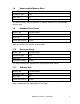
1.183 Unknown SAC Type Alarm Field Possible Values Resource Type SS7 SAC Dials Out Yes Perceived Severity Major This alarm indicates that the SLSA manager is unable to determine the SAC type for the SAC. It might be because of a hardware problem on the SAC. 1.184 Adapter Type Mismatch Alarm Field Possible Values Resource Type SWAN Adapter/SWAN 2 Adapter Dials Out No Perceived Severity Minor This alarm indicates that the adapter is not configured in SCF as the correct type. 1.
1.187 Power Supply Failure Alarm Field Possible Values Resource Type SWAN Adapter Dials Out Yes Perceived Severity Major This alarm indicates that the –5 volt power supply has failed. 1.188 SWAN Memory Error Alarm Field Possible Values Resource Type SWAN Adapter/SWAN 2 Adapter Dials Out Yes Perceived Severity Major This alarm indicates that a checksum or memory error occurred in the SWAN concentrator. 1.
1.191 SWAN IOP Line Parameter Error Alarm Field Possible Values Resource Type SWAN Adapter/SWAN 2 Adapter Dials Out Yes Perceived Severity Major This alarm indicates that a WAN IOP line parameter error occurred. 1.192 SWAN Download Error Alarm Field Possible Values Resource Type SWAN Adapter/SWAN 2 Adapter Dials Out Yes Perceived Severity Major This alarm indicates that a DLC task cannot be downloaded to a CLIP. 1.
1.195 Path B Down Alarm Field Possible Values Resource Type SWAN CLIP/SWAN 2 CLIP Dials Out Yes Perceived Severity Major This alarm indicates that path B from the LAN adapter to the CLIP is down. 1.196 CRU Storage Initialization Failed Alarm Field Possible Values Resource Type PMF/IOMF/PMF2/IOMF2/SNDA Dials Out Yes Perceived Severity Major This alarm indicates that the storage subsystem has failed to initialize the CRU. 1.
1.199 Path Switch Alarm Field Possible Values Resource Type Disk Dials Out Yes Perceived Severity Major This alarm indicates that an unexpected disk path switch has occurred. 1.200 Processor Switch on I/O Process Alarm Field Possible Values Resource Type Disk/Tape Dials Out No Perceived Severity Minor This alarm indicates that the disk process has been switched from the primary process to backup process. 1.
1.203 Both Paths Down Alarm Field Possible Values Resource Type Disk Dials Out Yes Perceived Severity Major This alarm indicates that both the primary and backup paths to the disk are down. This has resulted in the disk being inaccessible. 1.204 Data Integrity Error Alarm Field Possible Values Resource Type Disk Dials Out Yes Perceived Severity Critical This alarm indicates that a checksum error has occurred on the disk drive. 1.
1.207 Maximum Sector Rewrites For Period Exceeded Alarm Field Possible Values Resource Type Disk Dials Out Yes Perceived Severity Major This alarm indicates that disk has reached the maximum number of spared rewrites allowable in 24 hours. The disk is usable, but should be tested for hardware errors. 1.
1.211 Predictive Failure Analysis Threshold Reached For Recovered Errors Alarm Field Possible Values Resource Type Disk Dials Out No Perceived Severity Major This alarm indicates that the Predictive Failure Analysis threshold for recovered errors has been reached for the disk. 1.212 Recovered Error Alarm Field Possible Values Resource Type Disk Dials Out Yes Perceived Severity Major This alarm indicates that a recovered error occurred on the disk drive.
1.215 Peripheral Device Write Fault Error Alarm Field Possible Values Resource Type Disk Dials Out Yes Perceived Severity Minor This alarm indicates that a peripheral device write fault error occurred on the disk drive. 1.216 Track Following Error Alarm Field Possible Values Resource Type Disk Dials Out Yes Perceived Severity Major This alarm indicates that a track following error occurred on the disk drive. 1.
1.219 Medium Error Alarm Field Possible Values Resource Type Disk Dials Out Yes Perceived Severity Critical This alarm indicates that a medium error occurred on the disk drive. 1.220 Software Error Alarm Field Possible Values Resource Type Disk Dials Out Yes Perceived Severity Minor This alarm indicates that a software error occurred on the disk drive. 1.
1.223 Backup Power Supply Failure in External Disk Module Alarm Field Possible Values Resource Type External Disk Collection Dials Out Yes Perceived Severity Major This alarm indicates that the backup power supply in the external disk module is either not present or has failed. 1.
1.226 SCSI Bus Termination Power Failure in External Disk Module Alarm Field Possible Values Resource Type External Disk Collection Dials Out Yes Perceived Severity Major This alarm indicates that the SCSI bus termination power failure has been detected in the external disk module. 1.227 Not Communicating Alarm Field Possible Values Resource Type Storage Router Dials Out Yes Perceived Severity Major This alarm indicates that the storage router is not communicating. 1.
1.230 Tape Path Down Alarm Field Possible Values Resource Type Tape Dials Out Yes Perceived Severity Major This alarm indicates that the tape path has gone down unexpectedly.
Section 2 OSM Alarms for HP Integrity NonStop Servers This section describes OSM alarms that are unique to HP Integrity NonStop NS-series servers on H06.05 (OSM T0682 H02 AAN) & later. 2.
2.4 PE NonStop Blade Element Id Incompatibility Alarm Field Possible Values Resource Type NonStop Blade Element Dials Out Yes Perceived Severity Major This Alarm is generated because not all PEs of this NonStop Blade Element have the same NonStop Blade Element ID. 2.
2.8 Invalid Reintegration Cable Connections. Alarm Field Possible Values Resource Type NonStop Blade Element Dials Out Yes Perceived Severity Major This Alarm is generated when not all incoming NonStop Blade Element reintegration board cables to this NonStop Blade Element come from the same upstream NonStop Blade Element. 2.
2.12 NonStop Blade Element Not Cabled to NonStop Blade Complex Alarm Field Possible Values Resource Type NonStop Blade Element Dials Out Yes Perceived Severity Major This Alarm is generated when the NonStop Blade Element reintegration board cables for the complex form a ring topology, but this NonStop Blade Element has been excluded. 2.
2.16 Power Redundancy Loss Alarm Field Possible Values Resource Type NonStop Blade Element Dials Out Yes Perceived Severity Major This Alarm is generated when the NonStop Blade Element has lost power redundancy. 2.
2.20 NonStop Blade Element Fan Assembly (Slot %d) Hardware Error Alarm Field Possible Values Resource Type NonStop Blade Element Dials Out Yes Perceived Severity Major This Alarm is generated when the fan assembly/fan/power supply/power supply fan of a NonStop Blade Element experiences a hardware fault. 2.
2.24 Temperature Exceeded Normal/Critical Limits Alarm Field Possible Values Resource Type NonStop Blade Element Dials Out Yes Perceived Severity Minor This alarm is raised when: The NonStop Blade Element temperature has exceeded normal/critical limits. 2.25 Temperature Sensor Not Responding Alarm Field Possible Values Resource Type NonStop Blade Element Dials Out Yes Perceived Severity Minor This alarm is raised when The NonStop Blade Element temperature sensor is not responding. 2.
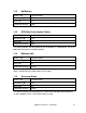
2.28 Power Supply Hardware Fault Alarm Field Possible Values Resource Type NonStop Blade Element power supply Dials Out Yes Perceived Severity Major This alarm is raised when the power supply experienced a hardware fault. 2.29 Loss of AC Power Alarm Field Possible Values Resource Type NonStop Blade Element power supply Dials Out Yes Perceived Severity Major This alarm is raised when the AC Power State for the power supply is down. 2.
2.32 PE LID Mismatch Detected Alarm Field Possible Values Resource Type LSU Dials Out Yes Perceived Severity Major This alarm is raised when a LID mismatch is detected in Processor Element configuration for a processor. 2.33 PE Memory Size Mismatch Detected Alarm Field Possible Values Resource Type LSU Dials Out Yes Perceived Severity Major This alarm is raised when a memory size mismatch is detected in Processor Element configuration for a processor.