
Avoiding Connector and Backplane Damage During CRU/FRU Replacement


2
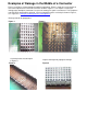
Inspect CRU/FRU Connectors
Using a flashlight, examine the connector shell and the sockets.
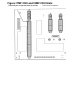
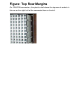
Examine the perimeter of the shell for small notches, scrapes, and
indentations. On PMF CRUs and IOMF CRUs, pay particular
attention to the shell immediately above the 3 right sockets on the
top row (facing the connector). This section of the shell is more
susceptible to damage because the margins (distance) between
the top of the shell and the socket windows are thinner here. See
Top Row Margins and Examples of CRU/FRU Connector
Damage.
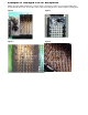
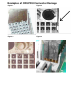
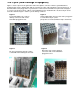
Check the sockets for damage. On PMF CRUs and IOMF CRUs,
pay particular attention to the 3 right sockets on the top row,
where damage most commonly occurs. Check the windows for
punctures, deformations, and obstructions. See Examples of
CRU/FRU Connector Damage.
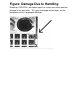
If any damage is found, replace the CRU/FRU. Locate all slots
where the unit has been installed and inspect those backplane
connectors as described in Step 1. Describe the damage and its
location in Genesis and on the Part Return Tag (PRT).
This procedure should be performed as part of every CRU/FRU
replacement. There is no need to inspect a working system for connector
damage.