Replacing an ATM3SA CRU This procedure describes how to replace an ATM3 ServerNet adapter (ATM3SA) CRU in a NonStop S-series server online. You might need to replace an ATM3SA CRU if it has failed or partially failed. You do not need to shut down the system before replacing an ATM3SA CRU. Caution: If a previously installed ATM3SA CRU and backplane connectors have damaged pins, remove the ATM3SA CRU and install a filler panel in the vacant slot. Attach red tags to the filler panel to identify the slot.
7 Label the communications cables connected to the ATM3SA CRU to be replaced. Replace the ATM3SA CRU: 1 Remove the ATM3SA CRU to be replaced. 2 Inspect the new ATM3SA CRU and backplane. 3 Install the new ATM3SA CRU. Note: Wait a minimum of 30 seconds after removing the old ATM3SA CRU before installing the new ATM3SA CRU. 4 Check the installation of the new ATM3SA CRU. Resume Operations: 1 Start the new ATM3SA CRU. 2 Restart the communications lines.
Standard Operating Practices Caution. Replace only one CRU or FRU at a time. Attempting to replace more than one hardware component at a time might cause serious system outages, processor halts, and connectivity problems. Whenever you replace a CRU or a FRU, use the following standard operating practices to minimize any potential damage to the equipment: ● Complete HP training courses on system support for NonStop S-series servers.
For example, if your computer room has an ambient room temperature of 25°C (77°F) and is at an altitude of 1,524 meters (5,000 feet), you have approximately 38 minutes to replace or reinstall the second fan before components inside a system enclosure overheat.
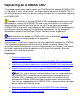
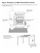
ESD Guidelines Figure: Working in an ESD-Protected Environment Observe the following electrostatic discharge (ESD) guidelines whenever servicing electronic components: ● Obtain an ESD protection kit and follow the directions that come with the kit. You can purchase an ESD kit from HP (T99247-A00) or from a local electronics store. Ensure that your ESD wriststrap has a built-in series resistor and that the kit includes an antistatic table mat.
Figure: Working in an ESD-Protected Environment This figure illustrates how to use an ESD kit when servicing customer-replaceable units (CRUs) and field-replaceable units (FRUs).
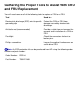
Gathering the Proper Tools to Assist With CRU and FRU Replacement You will need some or all of the following tools to replace a CRU or a FRU: Tool Used to... Electrostatic discharge (ESD) wriststrap with grounding clip Protect the CRU or FRU from damage caused by electrostatic discharge. Antistatic mat (recommended) Provide a static-free environment for removal and installation of a CRU or FRU. Flashlight Check the connectors for bent or broken pins.
Identifying the Communications Lines That Use an ATM3SA CRU The Asynchronous Transfer Mode (ATM) subsystem provides access to the ATM ServerNet adapter (ATM3SA) CRU. The following NonStop subsystems and utilities may be configured to access an ATM3SA CRU through the ATM subsystem: ● ● The TCP/IP subsystem, which can interface to the ATM subsystem to provide connectivity to TCP/IP networks.
1 Determine the TCP/IP processes, subnets, and Internet Protocol (IP) addresses associated with the ATM line on the ATM3SA CRU. Use the SCF INFO SUBNET command: INFO SUBNET $*.* Scan the output of the command for the name of the ATM line object associated with the ATM3SA CRU and then find the associated TCP/IP processes, subnets, and IP addresses. Make a note of this information. Note: The ATM line name is the same as the ATM3SA CRU (adapter) name. The example shows the output of this command.
Figure: How NonStop Subsystems and Utilities Access an ATM3SA CRU
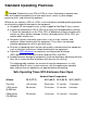
ATM3SA CRU Planning Worksheet Print this worksheet and use it to record information about an ATM ServerNet adapter (ATM3SA) CRU.
Example: Determining the TCP/IP Processes and IP Addresses for an ATM Line This is an example of the SCF INFO SUBNET command: ->INFO SUBNET $*.* TCPIP Info SUBNET \JULIE.$ZTC01.* Name Devicename #LOOP0 \NOSYS.$NOIOP #SN1 \JULIE.L018 #SN2 \JULIE.$AM2 *IPADDRESS 127.0.0.1 172.16.35.15 172.16.192.
Example: Identifying the Expand-Over-IP and Expand-Over-ATM Lines on a System This is an example of the SCF LISTDEV command display for single Expand-over-IP and Expand-over-ATM lines: ->LISTDEV TYPE 63,0 LDev Name PPID 109 $ATMLH 3,9 159 $IPCORE 0,16 BPID 2,7 1,15 Type Rsize Pri (63,0) 3 199 (63,0) 3 199 Program \COWBOY.$DATA00.T9057ADJ.LHOBJ \COWBOY.$DATA00.T9057ADJ.LHOBJ In this example, one Expand-over-ATM line (named $ATMLH) and one Expand-over-IP line (named $IPCORE) are configured on the system.
Example: Determining the Expand Lines That Use an ATM3SA CRU This is an example of the SCF INFO LINE command with the DETAIL option for an Expand-over-ATM line that uses a permanent virtual circuit (PVC): -> INFO LINE $ATMH, DETAIL EXPAND Detailed Info LINE $ATMH *Associatedev...$AM2 *Associatesubdev #IP Rsize........ 3 *Speed.......... 74666 Delay......... 0:00:00.10 Framesize.... 132 Txwindow....... 7 *Timeinactivity 0:00:00.00 *Maxreconnects 0 *Timerreconnect 0:00:30.
this example, the Expand-over-IP line named $IPYEA uses the TCP/IP process named $ZTC23 and the IP address 172.17.203.37.
Quiescing Customer Applications 1 Notify end users that applications will be temporarily unavailable. 2 Perform any actions necessary to quiesce customer applications. Note: The actions required to perform this step depend on the customer's application.
Stopping the Communications Lines That Use an ATM3SA CRU 1 Stop the activity on the lines. Use the SCF ABORT LINE command to stop the activity on a single line: ABORT LINE $ Use the SCF ABORT PATH command to stop the activity on all the lines in an Expand multiline path: ABORT PATH $ 2 Verify that the lines are in the STOPPED state.
5 Stop the TCP/IP subnets associated with the Asynchronous Transfer Mode (ATM) line on the ATM ServerNet adapter (ATM3SA) CRU. Caution: Make sure that the TACL session from which you are issuing SCF commands is not running on the one of the subnets that you are about to stop. Use the SCF STOP SUBNET command: STOP SUBNET $.# 6 Verify that the TCP/IP subnets are in the STOPPED state. Use the SCF STATUS SUBNET command: STATUS SUBNET $.
Example: Verifying That a Line Is Stopped This is an example of the SCF STATUS LINE command: -> STATUS LINE $LINE1 EXPAND Status LINE Name $LINE1 State STOPPED PPID 2, 10 BPID 3, 7 CIU-Path A ConMgr-LDEV 91 Note that the line is in the STOPPED state. This is an example of the SCF STATUS PATH command: -> STATUS PATH $PATH EXPAND Name $PATH Status PATH State STOPPED PPID 2, 15 BPID 3, 15 Note that the path is in the STOPPED state.
Example: Verifying That a WAN Subsystem IOP Is Stopped This is an example of the SCF STATUS DEVICE command: -> STATUS DEVICE $ZZWAN.#LINE1 WAN Manager STATUS DEVICE for DEVICE \COWBOY.$ZZWAN.#LINE1 State :........ STOPPED LDEV number.... 110 PPIN........... 2 ,13 BPIN......... 3 ,14 Note that the WAN subsystem input/output process (IOP) is in the STOPPED state.
Example: Verifying That a TCP/IP Subnet Is Stopped This is an example of the SCF STATUS SUBNET command: -> STATUS SUBNET $ZTC01.#SN2 TCPIP Status SUBNET \COWBOY.$ZTC01.#SN2 Name Status #SN2 STOPPED Note that the subnet is in the STOPPED state.
Determining the Physical Location of an ATM3SA CRU Use the SCF INFO ADAPTER command: INFO ADAPTER $ Scan the output of the command for the group, module, and slot location. Record this information in your log book. The example shows the output of this command.
Example: Determining the Location of an ATM3SA CRU This is an example of using the SCF INFO ADAPTER command: -> INFO ADAPTER $AM2 ATM Info ADAPTER \HANSOLO.$AM2 LOCATION (grp,mod,slot).. 1, 1, 53 ACCESSLIST................. 1, 3 AMP Filename (is use)...... \HANSOLO.$SYSTEM.SYS01.AMP *AMPFILENAME............... $SYSTEM.SYS*.AMP DownLd Filename (in use)... \HANSOLO.$SYSTEM.SYS01.C7838P00 *DLFILENAME................ $SYSTEM.SYS*.C7838P00 DownLd File Version........
Aborting an ATM3SA CRU 1 Abort the ATM3 ServerNet adapter (ATM3SA) CRU ADAPTER object and its subordinate objects. You can use SCF, the OSM Service Connection, or TSM Service Application to perform this step. Using SCF: Use the SCF ABORT ADAPTER command with the SUB ALL option: ABORT ADAPTER $, SUB ALL The SUB ALL option aborts the ADAPTER object and all its subordinate objects. Using OSM or TSM: 1. In the tree pane, select the ATM3SA CRU. 2. Select Display> Actions. 3. Click Abort. 4.
Example: Verifying That the ADAPTER Object for an ATM3SA CRU Is Stopped This is an example of using the SCF STATUS ADAPTER command: -> STATUS ADAPTER $AM2 ATM Status ADAPTER Name $AM2 State STOPPED Substate UNKNOWN Trace OFF Time Loaded 10 Feb 1998, 11:00 Note that the ADAPTER object is in the STOPPED state.
Labeling Communications Cables for an ATM3SA CRU 1 Find the group, module, and slot in which the ATM ServerNet adapter (ATM3SA) CRU is installed. The figure shows the the ATM3SA CRU slot locations. 2 Tag each fiber optic cable connected to the ATM3SA CRU with a physical label, preferably at both ends. The label should include the following information: ● The logical device name assigned to the Asynchronous Transfer Mode (ATM) line. For example, $ATM2.
Figure: ATM3SA CRU External Indicators
Removing an ATM3SA CRU Note: Whenever you handle an ATM ServerNet adapter (ATM3SA) CRU, you should follow standard operating practices to avoid damage to the equipment. 1 Disconnect the fiber optic cables from the ATM3SA CRU.
Figure: Grounding Clip Connected to PMF CRU or IOMF CRU Ventilation Holes
Figure: Removing an ATM3SA CRU
Inspecting an ATM3SA CRU Note: Whenever you handle an ATM ServerNet adapter (ATM3SA) CRU, you should follow standard operating practices to avoid damage to the equipment. Visually inspect the ATM3SA CRU and the backplane connector for damage. Use a flashlight, if necessary, to check for bent or broken pins. You can damage pins by bumping or jamming the ATM3SA CRU's shell against a surface, which can partially close the hole in the connector-pin socket.
Installing an ATM3SA CRU Note: Whenever you handle an ATM ServerNet adapter (ATM3SA) CRU, you should follow standard operating practices to avoid damage to the equipment. 1 Put on the electrostatic discharge (ESD) wriststrap and attach the grounding clip to the antistatic mat. 2 Place the package containing the ATM3SA CRU on the antistatic mat. 3 Caution: When opening the packing container, be careful not to cut into the ESD protective bag. Open the packing container and remove the ATM3SA CRU.
8 Caution: Apply equal pressure to both the top and bottom of the ATM3SA CRU when pushing it into the slot to avoid damaging the connector pins. If pins are damaged, both the ATM3SA CRU and the backplane (or enclosure) must be replaced. Push the ATM3SA CRU to the rear of the slot, but don't force it. The figure shows how to install an ATM3SA CRU. 9 Press the blue-green tab on the ATM3SA CRU ejector and latch the ejector to seat the ATM3SA against the backplane.
Figure: Installing an ATM3SA CRU
Figure: ATM3SA CRU Hardware Connection
Checking the Installation of an ATM3SA CRU 1 Make sure that the power-on LED (green light) is on. Note: The fault LED (amber light) flashes when the ATM ServerNet adapter (ATM3SA) CRU is installed and continues to flash while the condition of the ATM3SA CRU is tested. The test that is executed is the power-on self-test (POST). The fault LED goes off when the POST successfully finishes. The figure shows the location of the power-on LED and fault LED.
Starting an ATM3SA CRU Note: An ATM ServerNet adapter (ATM3SA) CRU usually starts automatically within a few minutes after it has been installed. 1 Verify that the ATM3SA CRU ADAPTER object is in the STARTED state. Use the SCF STATUS ADAPTER command: STATUS ADAPTER $ The example shows the status of the ADAPTER object. 2 If the ATM3SA CRU ADAPTER object is in the STOPPED state, start it and its subordinate objects. You can use SCF, OSM, or TSM to perform this step.
1. From the Display menu, choose Firmware Update. The Firmware Update dialog box is displayed. 2. From the Resource type menu, choose ATM CRU. 3. From the Display menu, select Down-rev to display the ATM3SA CRUs to be updated. A list of resources whose firmware is older than the version of the SYSnn is displayed in the Available list box. If the ATM3SA CRU appears in the Available list box, do the following to update its firmware: 1. Select the ATM3SA CRU and click Add to include it in the Selected window.
Example: Verifying That the ADAPTER Object for an ATM3SA CRU Is Started This is an example of using the SCF STATUS ADAPTER command: ->STATUS ADAPTER $AM2 ATM Status ADAPTER Name $AM2 State STARTED Substate OPERATIONAL Trace OFF Time Loaded 10 Feb 1998,.. Note that the ADAPTER object is in the STARTED state.
Starting the Communications Lines That Use an ATM3SA CRU 1 Start the TCP/IP subnets. Use the SCF START SUBNET command: START SUBNET $.# 2 Start the WAN subsystem input/output processes (IOPs). Use the SCF START DEVICE command: START DEVICE $ZZWAN.# 3 Start the lines.
Verifying That the Communications Lines That Use an ATM3SA CRU Are Started 1 Verify that the TCP/IP subnets are started. Use the SCF STATUS SUBNET command: STATUS SUBNET $.# The example shows the output of this command. 2 Verify that the WAN subsystem input/output processes (IOPs) are started. Use the SCF STATUS DEVICE command: STATUS DEVICE $ZZWAN.# The example shows the output of this command. 3 Verify that the lines are started.
Example: Verifying That a TCP/IP Subnet Is Started This is an example of the SCF STATUS SUBNET command: -> STATUS SUBNET $ZTC01.#SN2 TCPIP Status SUBNET \COWBOY.$ZTC01.#SN2 Name Status #SN2 STARTED Note that the subnet is in the STARTED state.
Example: Verifying That a WAN Subsystem IOP Is Started This is an example of the SCF STATUS DEVICE command: -> STATUS DEVICE $ZZWAN.#LINE1 WAN Manager STATUS DEVICE for DEVICE \COWBOY.$ZZWAN.#LINE1 State :........ STARTED LDEV number.... 110 PPIN........... 2 ,13 BPIN......... 3 ,14 Note that the WAN subsystem input/ouput process (IOP) is in the STARTED state.
Example: Verifying That a Line Is Started This is an example of the SCF STATUS LINE command: -> STATUS LINE $LINE1 EXPAND Name $SATHO0 Status LINE1 State STARTED PPID 2, 10 BPID 3, 7 CIU-Path A ConMgr-LDEV 91 Note that the line is in the STARTED state. This is an example of the SCF STATUS PATH command: -> STATUS PATH $PATH EXPAND Name $PSHOT Status PATH State STARTED PPID 2, 15 Note that the path is in the STARTED state.
Resuming Customer Applications 1 Perform any actions necessary to resume customer applications. Note: The actions required to perform this step depend on the customer's application. 2 Notify end users that applications are now available.
Viewing the Operator Log ($0) Using the OSM or TSM Event Viewer You can use either the OSM or the TSM Event Viewer to view $0. Using OSM 1 From a system console, launch the OSM Event Viewer or by doing one of the following: ● From the Start button: a. Select: Start>Programs>HP OSM>OSM Event Viewer. The OSM Event Viewer Home Page appears. b. Select a system. ● From the OSM Service Connection: a. Log on to the server using the OSM Service Connection b. Select Tools>Event Viewer.
Using TSM 1 From a system console, launch the TSM Event Viewer Application by doing one of the following: ● From the Start button, select: ● ● ❍ For TSM client software Versions 2000A and later: Start>Programs> Compaq TSM>TSM Event Viewer ❍ For TSM client software Versions 10.0 and earlier: Start>Programs>TSM Client> TSM Event Viewer Log on to the server using the TSM Service Application and select Display>Events. Open the TSM Low-Level Link and select Display>Events.
TSM Event Viewer.
Viewing the Service Log ($ZLOG) Using the OSM or TSM Event Viewer You can use either the OSM or the TSM Event Viewer to view $ZLOG. Using OSM 1 From a system console, launch the OSM Event Viewer or by doing one of the following: ● From the OSM Service Connection: a. Log on to the server using the OSM Service Connection b. Select Tools>Event Viewer. ● From the Start button: a. Select: Start>Programs>HP OSM>OSM Event Viewer. The OSM Event Viewer Home Page appears. b. Select a system.
Using TSM 1 From a system console, launch the TSM Event Viewer Application by doing one of the following: ● From the Start button, select: ● ● ❍ For TSM client software Versions 2000A and later: Start>Programs> Compaq TSM>TSM Event Viewer ❍ For TSM client software Versions 10.0 and earlier: Start>Programs>TSM Client> TSM Event Viewer Log on to the server using the TSM Service Application and select Display>Events. Open the TSM Low-Level Link and select Display>Events.
TSM Event Viewer.
Managing the Windows NT Event Viewer Application Log The event viewer has 3 logs: an Application log, a Security log, and a System log. Each log can contain a limited number of entries; for example, 512 KB. The Application log can hit the maximum size when you are running the TSM service application or performing a system discovery using the TSM Low-Level Link. Note: OSM is not supported on workstations running the Windows NT operating system.
Managing the Windows Event Viewer Application Log The event viewer has 3 logs: an Application log, a Security log, and a System log. Each log can contain a limited number of entries; for example, 512 KB. The Application log can hit the maximum size when you are running the TSM Service Application (but not the OSM Service Connection) or performing a system discovery using the OSM or TSM Low-Level Link. To prevent a log from becoming full, clear or reconfigure the log.
6 Select an option under When the maximum log size is reached: ● Overwrite events as needed. ● Overwrite event older than xx days (default= 7 days). ● Do not overwrite events (clear log manually). 7 Click Clear Log to put the new settings into effect. A message appears "Do you want to save xx Log before clearing it?" Click Yes to save the log entries. Click No to permanently discard the entries. 8 Click OK to close the xx Log Properties window.. 9 Close the Event Viewer window.