
Installation Guide, Second Edition - HP Integrity rx1620


Chapter 3
Installing and Configuring
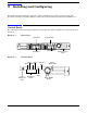
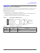
Control Panel
16
Table 3-1 Control Panel LEDs and Switches
Name Function
Power On/Off
LED
The green on/off LED is illuminated when the power is on.
Power On/Off
Button
This is the power on/off switch for the server.
System LED The System LED provides information about the system status. When operation is
normal, the LED is green. When there is a system warning, the LED is flashing yellow.
When there is a system fault, the LED is flashing red.
a
a. See the troubleshooting chapter for details on information provided by the system and diagnostic
LEDs.
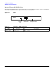
LAN LED The LAN LED provides status information about the LAN interface. When the LAN LED
is flashing, there is activity on the LAN.
Diagnostic
LED 1
The four diagnostic LEDs operate in conjunction with the system LED to provide
diagnostic information about the system.
a
Diagnostic
LED 2
The four diagnostic LEDs operate in conjunction with the system LED to provide
diagnostic information about the system.
a
Diagnostic
LED 3
The four diagnostic LEDs operate in conjunction with the system LED to provide
diagnostic information about the system.
a
Diagnostic
LED 4
The four diagnostic LEDs operate in conjunction with the system LED to provide
diagnostic information about the system.
a
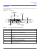
Locator
Button and
LED
The locator button and LED are used to help locate this server within a rack of servers.
When the button is engaged, the blue LED illuminates and an additional blue LED on
the rear panel of the server illuminates. This function may be remotely activated.