
Installation Guide, Second Edition - HP Integrity rx1620

Chapter 3
Installing and Configuring
Installing Processors and Memory
27
Observe all ESD safety precautions before attempting this procedure. Failure to follow ESD
safety precautions could result in damage to the server.
Avoid contact with the processor heatsink if the server has been operating prior to the
installation of the additional processor. The heatsink will be safe to touch after the cover has
been removed for a few seconds.
Installing an Additional Processor
CAUTION Ensure that the cache size is identical for all processors. Failure to observe this caution will
result in system failure.
Ensure that all processors are rated for use at the same speed. Failure to observe this caution
will result in performance degradation.
Valid processors are identified in “Parts Information” in the hp Integrity rx1620 Maintenance
Guide.
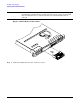
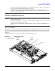
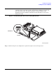
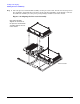
Processor Load Order
Processors are located on the system board. The system board can support either one or two processors. CPU
0 is located to the right of the system board and CPU 1 (when installed) is located on the left of the system
board next to the bridge assembly. In a single CPU configuration, the single processor must be installed in
CPU 0 slot.
Each processor has an associated power pod that is required by the processor.
Figure 3-12 Processor Location
Rear of Chassis
POWER
POD
CPU 0
POWER
POD
CPU 1
CPU 0
CPU 1