
Installation Guide, Second Edition - HP Integrity rx1620


Chapter 3
Installing and Configuring
Optional Management Processor Card (MP)
43
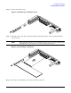
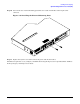
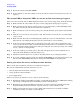
Step 4. Remove the blank retaining tab out of its socket on the system chassis and remove the blank from
the system.
Figure 3-28 Removing the MP Card Blank
Step 5. Remove the insulator between the battery and the battery socket on the management processor
card.
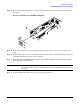
Step 6. Align the MP card over the two mounting posts on the system board and align the three connectors
of the MP card with the cutouts on the rear panel.
Step 7. Carefully push the 10/100 Management LAN, 15-pin VGA and 25-pin serial connectors through
their openings on the rear panel.
CAUTION Special care should be used when mating the connectors of the MP card with the
sheet metal of the rear panel. It is possible to damage the EMI gasket of the RJ-45 of
the card.
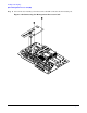
Step 8. Connect the MP card cable to its connector on the system board.