
Operations Guide, Fourth Edition - HP Integrity rx1620
• Unified L2 cache:
— 256 KB, 8-way set associative
— 128 byte line size
• Unified L3 cache:
— 3MB, 12-way set associative (1 GHz)
— 1.5 MB, 6-way set associative (900 MHz)
— 128 byte line size
Processor Bus
The processor bus (Front Side Bus, FSB) in this product runs at 200 MHz. Data on the FSB are
transferred at a double data rate, which allows a peak FSB bandwidth of 6.4 GB/sec.
I/O and Memory Controller
The hp Integrity rx1620 Server supports the following features of the I/O and memory controller
chip:
• 3.3 GB/s peak IO bandwidth.
• provides 7 communication paths.
• Peak memory bandwidth of 8.5 GB/s.
• 2 memory cells, 144 data bits each.
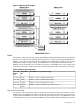
Memory Architecture
The memory subsystem includes the memory controller and the DDR SDRAM memory DIMMs,
along with the memory bus traces and required termination. The memory subsystem provides
two memory cells, 144 bits wide each (128 bits of data, 16 bits of ECC). Each cell can accommodate
up to 6 DIMM slots; however, in Nemesis, power limitations restrict the total loaded DIMM
count to 6. Two of the DIMMs connect to cell 0, and the other 4 DIMM slots connect to cell 1. For
early Nemesis prototypes, 8 DIMM connectors will be loaded onto system boards to facilitate
power characterization; if actual power consumption is low enough, a change request could be
entertained to increase the DIMM count to 8.The memory bus clock speed is 125MHz, and the
data transfer rate is 250Mtransfers/second as data is transmitted on both edges of the clock. The
peak data bandwidth for this memory subsystem design is 8 GB/s. DIMMs must be loaded in
pairs. Memory is protected by data error correcting codes (ECC). The hardware implementation
supports the chip-spare for specific four-DIMM configurations.The minimum amount of memory
that can be installed is 512MB (2-256MB DIMMs). The maximum amount of memory that can
be installed is dependent on the largest DIMM size (density) qualified for use. 16GB is the
maximum memory (based on 2GB DIMMs).The DIMMs used must be low-profile (1.2") DIMMs,
to fit into the 1U chassis. The DIMMs are standard DDR2100 registered DIMMs. Only DIMMs
qualified by HP for the hp Integrity rx1620 Server platform will be supported.
Architecture
The memory interface supports two DDR cells, each of which is 144 data bits wide. The memory
subsystem physical design uses a comb-filter termination scheme for both the data and
address/control buses. This part of the topology is similar to other DDR designs in the computer
industry. Clocks are distributed directly from the memory interface; each clock pair drives 2
DIMMs. Memory data is protected by Error Correcting Code (ECC). 8 ECC bits per DIMM protect
64 bits of data. The use of ECC allows correction of single-bit errors, and detection of multi-bit
errors. DIMMs without ECC will not be qualified or supported.The memory subsystem features:
address parity, address buffering, clock buffering, and industry standard SPD (Serial Presence
Detect), IEEE 1149.1 Boundary Scan, and power bypassing near the memory components. The
memory features x4 chip-spare and x8 detect. The memory subsystem does not support hot
spare, mirroring, or hot-plug. The memory subsystem uses 1x direct attach mode, and does not
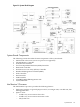
use multiplexers.The Memory Block Diagram indicates the recommended load order for DIMM
pairs; DIMM0A/B should be loaded first, followed by DIMM1A/B, and so on.
114 System Information