
Operations Guide, Fourth Edition - HP Integrity rx1620
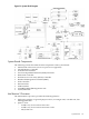
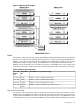
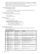
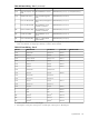
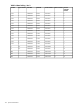

Figure B-2 Memory Block Diagram
DIMMs
The memory subsystem will only support DDR SDRAM (Double Data Rate Synchronous Dynamic
Random Access Memory) technology utilizing industry-standard PC2100 type DDR SDRAM
DIMMs, 1.2" tall. This is expected to be the standard height available at first release and is currently
being used by high-volume products. The DIMMs use a 184-pin JEDEC standard connector.
DIMMs must be loaded in pairs. To enable chip sparing, four DIMMs of the same density must
be loaded with specific configuration rules. The following table summarizes memory solutions:
Table B-1 Memory Array Capacities
DDR SDRAM Count, Type and TechnologySingle DIMM
Size
Min. / Max
Memory
Size
DIMM 18 x 32Mb x 4 DDR SDRAMs (128Mb)256MB0.5GB / 3GB
DIMM 18 x 32Mb x 4 DDR SDRAMs (256Mb)512MB1GB / 4GB
DIMM 18 x 64Mb x 4 DDR SDRAMs (512Mb)1024MB2GB / 8GB
DIMM 36 x 128Mb x 4 DDR SDRAMs (512Mb, stacked)2048MB
DIMM
4GB / 16GB
Chip Spare Functionality
The memory subsystem design supports chip spare functionality. Chip spare enables an entire
SDRAM chip on a DIMM to be bypassed (logically replaced) in the event that a multi-bit error
is detected on that SDRAM. In order to use the chip spare functionality, only DIMMs built with
x4 SDRAM parts can be used, and these DIMMs must be loaded in quads (2 DIMMs per memory
System Board 115