
Operations Guide, Fourth Edition - HP Integrity rx1620
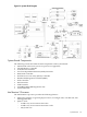
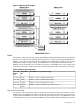
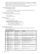
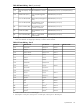
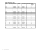

Table B-2 Data Pathing - Part 1 (continued)
ACPI PathPhysical LocationPCI Card InformationPCI Slot
(HWP0002,100) / PCI (1|1) / SCSI (Punx,Luny)Rear Bulkhead “LAN Gb”Ultra 3 SCSI (Core) - Ext.
SCSI
Core
(HWP0002,100) / PCI (2|0)Top Slot (full length PCI
slot)
1000 BT LAN (Core)Core
(HWP0002,400) / PCI (1|0)Bottom Slot (half length PCI
slot)
PCI-X 133 MHz/64 Bit1
(HWP0002,200) / PCI (1|0)Rear Bulkhead “Serial
Console” connector
PCI-X 133 MHz/64 Bit2
(HWP0002,700) / PCI (1|0)Rear Bulkhead “Serial
Console” connector
1
Serial Controller (MP)MP
(HWP0002,700) / PCI (1|1)Rear Bulkhead “VGA”
port
1
Console Port (MP)MP
(HWP0002,700) / PCI (2|0)Disk “0” - Right Hand
Internal Disk
VGA Controller (MP)MP
1 If using “W” cable P/N A6144-63001 it will break this port out to 3 x 9-pin RS-232 connectors labeled “Console”,
“UPS”, and “Remote”. If using 25-pin cable only “Console” will be available.
Table B-3 Data Pathing - Part 2
Windows PathLinux PathHP-UX PathMAPPER PathPCI Slot
00:01.00/0/1/0.1.20/0/1/0.0.0Core
00:01.00/0/1/00/0/1/0Core
00:01.10/0/1/1.1.2.30/0/1/1.0.0.0.0Core
00:01.10/0/1/10/0/1/1.0.0.0.1Core
00:01.20/0/1/20/0/1/2Core
00:02.00/0/2/00/0/2/0Core
0/0/2/0.0.0.00/0/2/0.0.0Core
20:01.00/1/1/00/1/1/0Core
0/1/1/0.0.00/1/1/0.0.0Core
0/1/1/0.1.00/1/1/0.1.0Core
20:01.10/1/1/10/1/1/1Core
0/1/1/1.x.y0/1/1/1.x.yCore
20:02.00/1/2/00/1/2/0Core
80:01.00/3
1
0/4
1
1
40:01.00/2
1
0/2
1
2
E0:01.00/4/1/0
2
0/7/1/0
1
MP
E0:01.10/4/1/1
2
0/7/1/1
1
MP
E0:02.00/4/2/0
1
0/7/2/0
1
MP
1 Conflict with HP-UX ioscan vs. ODE Mapper
2 0/4/1/0 port 0 = “UPS port”, 0/4/1/1 port 0 = “Console port”, 0/4/1/1 port 2 = “Remote port”
System Board 119