
Operations Guide, Fourth Edition - HP Integrity rx1620


4 Troubleshooting
This chapter provides troubleshooting instructions used in the maintenance of the hp Integrity
rx1620 Server.
Troubleshooting Tips
WARNING! Before removing a cover, always disconnect the AC power cord and unplug cables.
Disconnect the AC power cord to avoid exposure to high energy levels that may cause burns
when parts are short-circuited by metal objects such as tools or jewelry.
CAUTION: Do not operate the HP Server for more than 5 minutes with any cover (including
disk drives) removed. Damage to system components may result due to improper cooling airflow.
• For problems with an optional disk array controller board, refer to the appropriate manuals
provided with the array controller.
• For questions on the operation of HP e-DiagTools, refer to the HP e-DiagTools Administrator
Guide on the HP Web Site at http://docs.hp.com.
• For general information on HP Server products, refer to the HP Web Site and search for
“management” at http://docs.hp.com.
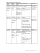
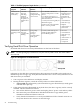
Troubleshooting Methodology
1. This is the entry point to the troubleshooting process. Here, you pick from a set of symptoms,
ranging from very simple (System LED is blinking) to the most difficult Machine Check
Abort (MCA) has occurred. The following is a list of symptom examples:
• System LED blinking
• System Alert present on console
• System will not power-up
• System will not boot
• Error/Event Message received
• Machine Check Abort (MCA) occurred
2. This step narrows down the observed problem to the specific troubleshooting procedure
required. Here, you isolate the failure to a specific part of the server so that you can perform
more detailed troubleshooting. For example:
• Problem-System LED blinking
— System Alert on console?
— Analyze the alert by using the system event log (SEL) to identify the last error
logged by the baseboard management controller. Use either the EFI shell command
line interface (CLI) or if the optional management processor card is installed, use
the MP commands to view the SEL.
3. At this point you will have a good idea about which area of the system requires further
analysis. For example, if the symptom was “system will not power-up” then the initial
troubleshooting procedure may have indicated a problem with the DC power supply not
coming up after the power switch was turned on.
4. You have now reached the point where the failed Field Replaceable Unit (FRU or FRUs)
have been identified and need to be replaced. You must now perform the specific remove
and replace and verification steps.
Troubleshooting Tips 73